


MSSM0709BE/9273BV (1 of 1)
È
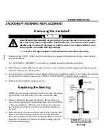
JACKSHAFT BEARING REPLACEMENT
Ê
Removing the Jackshaft
ELECTROCUTION HAZARD—High voltage is present inside electric boxes, mo-
tors, and many other components. Power switches on machine control panels
disable only control circuit power in certain boxes. You can be killed or seri-
ously injured on contact with high voltage.
☞
Lock OFF and tag out power at the wall disconnect before servicing.
Dual motor drive 30015, 30020, and 30022 machines are equipped with jackshafts. Replace worn bearings
as described below.
See “JACKSHAFT ASSEMBLY” (see Table of Contents) during the following procedures:
1. With the power locked OFF, remove the top console cover by prying out the four plugs and unscrewing the
four bolts. Remove the rear belt guard.
2. Loosen and remove the belts from the jackshaft. Remove the straight bore pulley, electric clutch and coil from
the jackshaft (for further information see “DRIVE TRAIN SERVICE” in the Table of Contents).
3. Remove the four jackshaft mounting screws.
Ê
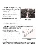
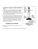
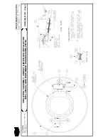
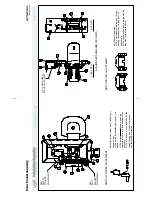
Replacing the Bearing
NOTE: Provide enough clearance around the bottom of the hous-
ing (FIGURE 1) as the bearing will come out with the shaft.
1. Remove and discard the shaft clip and place the assembly in a
press with the tapered shaft end pointing up as shown in FIGURE
1. Press the shaft down. When the lower bearing clears the hous-
ing, the shaft will drop out with the lower bearing remaining on
the shaft.
2. Place the shaft in the press and remove the bearing from the shaft.
Remove the outer retaining ring from the housing and discard.
Place the housing in the press with the bearing facing downward,
then press the bearing out. Remove the inner retaining ring and
discard all retaining rings.
3. Thoroughly clean all parts with solvent. The bearing housing
and shaft must be absolutely clean and free of dirt and ad-
hesives.
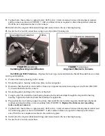
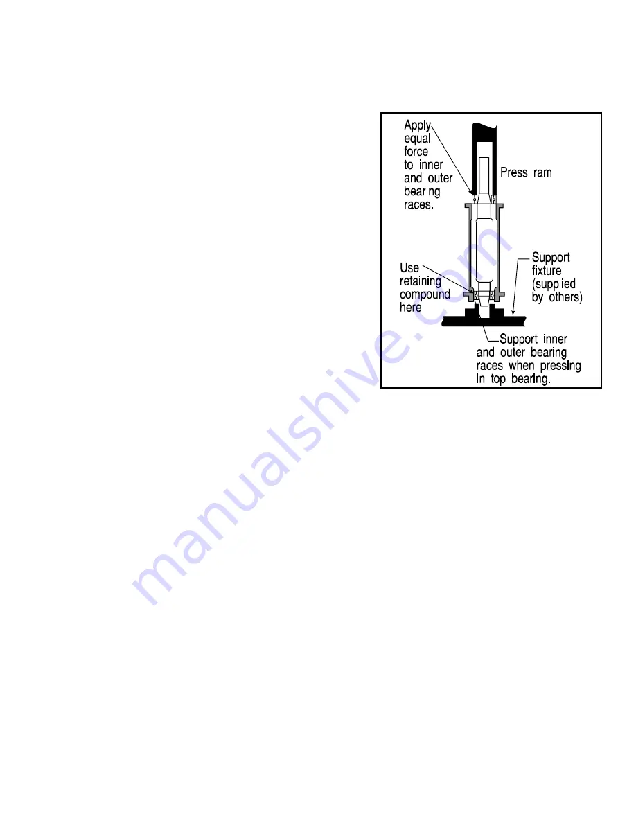
4. Install a new inner retaining ring inside the housing and apply a
small amount of retaining compound (Loctite 271 or similar)
around the bearing seating surface of the bearing housing as
shown in FIGURE 2. Press the new bearing in the housing, ap-
plying equal force to the inner and outer bearing races. Install a
new outer retaining ring in the housing.
5. Slide the other new bearing onto the shaft and place the shaft in-
side the housing with the tapered end into the installed bearing.
Place the assembly under the press with the housing completely
supported by the inner and outer race of the bearing as shown
in FIGURE 2. Simultaneously press the bearing onto the shaft
and into the housing until the bearing bottoms out, applying
equal force to both inner and outer bearing races. Install a new
shaft clip (tapered end only).
Ê
Installing the Jackshaft
1. Replace the jackshaft and all related components in reverse order
of disassembly.
2. Align pulleys and set belt tension as explained in “DRIVE TRAIN SERVICE”.
Î
FIGURE 1
(MSSM0709BE)
Î
Removing Jackshaft
Bearings
Î
FIGURE 2
(MSSM0709BE)
Î
Replacing Jackshaft
Bearings
B
Содержание 30015
Страница 6: ......
Страница 8: ......
Страница 10: ......
Страница 19: ...Section 1 Service and Maintenance ...
Страница 51: ...Section 2 Drive Assemblies ...
Страница 57: ...BMP920027 93251V Page 1 MOTOR MOUNT ASSEMBLY 30015 30020 30022 RIGID MOUNT WASHER EXTRACTORS DRIVE ASSEMBLIES ...
Страница 59: ...BMP950003 95107V Page 1 MOTOR MOUNT 30015 30020 S4A S4G S4J S4T ...
Страница 68: ......
Страница 69: ...Section 3 Bearing Assemblies ...
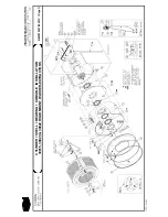
Страница 72: ...BMP910032 96141V Page 1 MAIN BEARING ASSEMBLY 30015C4x M4x K5x S5x ...
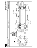
Страница 74: ...BMP910033 96141V Page 1 MAIN BEARING ASSEMBLY ...
Страница 76: ...BMP910034 95116V Page 1 MAIN BEARING ASSEMBLY 30015M6x ...
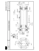
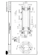
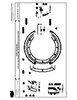
Страница 80: ...BMP910035 93251V Page 1 JACKSHAFT ASSEMBLY 30015 30020 30022 RIGID MOUNT WASHER EXTRACTORS ...
Страница 82: ......
Страница 83: ...Section 4 Shell and Door Assemblies ...
Страница 86: ...BMP920009 94491V Page 1 DOOR ASSEMBLY 30015 30020 RIGID MOUNT WASHER EXTRACTORS ...
Страница 90: ......
Страница 91: ...Section 5 Control and Sensing Devices ...
Страница 100: ...BMP920010 97281V Page 1 COIN ASSEMBLY INSTALLATION 240V 30015 30020 30022 COIN MACHINES ...
Страница 105: ...Section 6 Chemical Supply Devices ...
Страница 113: ...Section 7 Water and Steam Piping and Assemblies ...
Страница 114: ...ISOMETRIC SYMBOLS STANDARD SYMBOLS BMP920008 93027V Page 1 SCHEMATIC SYMBOLS KEY ...
Страница 115: ...BMP920015 96132V Page 1 WATER STEAM DRAIN SCHEMATICS 30015 30020 30022 RIGID MOUNT WASHER EXTRACTORS ...
Страница 132: ...BMP920021 93251V Page 1 STEAM INSTALLATION 30015 30020 30022 RIGID MOUNT WASHER EXTRACTORS ...
Страница 136: ...BMP920020 93251V Page 1 DRAIN VALVE INSTALLATION 30015 30020 30022 RIGID MOUNT WASHER EXTRACTORS ...
Страница 138: ...BMP920017 93251V Page 1 ELECTRIC DRAIN VALVE 30015 30020 30022 RIGID MOUNT WASHER EXTRACTORS ...
Страница 139: ...Section 8 Pneumatic Piping and Assemblies ...