
MSSMA408BE/9273BV
È
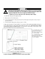
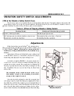
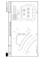
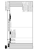
VIBRATION SAFETY SWITCH ADJUSTMENTS
Ë
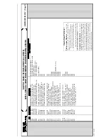
What the Vibration Safety Switch Does
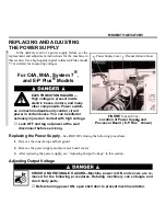
The vibration safety switch pictured below is an important safety feature. If properly adjusted, the switch will
momentarily actuate as a result of repeated machine movement caused by an out-of-balance condition. Table A
below illustrates the effect of the vibration safety switch actuation.
Ï
Table A—Effect of Tripping Vibration Safety Switch
Machine Model
Function of Vibration Safety Switch
30015, 30020, and 30022
Disables high speed extract
All microprocessor-controlled washer-extractors not
listed above, and all dye machines
De-energizes three-wire relay, effectively
terminating machine operation
Ê
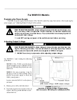
Adjustments
When the machine leaves Milnor
®
, the actuator arm is
tie-wrapped to prevent damage (except on 30015, 30020, and
30022 models). This tie wrap must be removed after the
machine is set into position but before the machine is op-
erated.
Adjustment of this switch from the factory setting is not
recommended; however, it should be checked for proper
functioning and adjusted if its proper setting is lost.
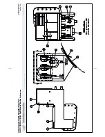
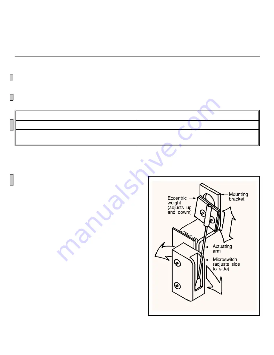
As shown at right in FIGURE 1, the unit consists of a
sensitive micro-switch with an extended actuating arm sup-
porting an eccentric weight. The weight may be adjusted by
moving it up and down on the arm and by rotating it on the
arm. In addition, the micro-switch itself may be tilted from
side to side.
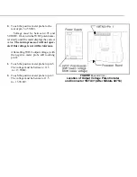
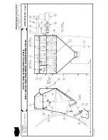
The sensitivity of the switch increases as the eccen-
tricweight is raised on the actuating arm and de-
creases as the weight is lowered.
The unit should be adjusted so that the actuating arm
will always reset by itself, this being accomplished by rotat-
ing either the switch or the weight to give just enough bias to
cause the switch to reset. Check the adjustment by moving the
arm to the left then slowly releasing it. Make sure the micro-
switch clicks when the arm is slowly released, thus indicating
that it has reset. In the released position the arm should rest lightly but definitely against the stop on the micro-switch
case that prevents any further arm movement to the left.
For machines with rigid mounted shells, where the machine is bolted to a very substantial foundation, very
little machine movement will occur for a given degree of out-of-balance. Under such conditions it may be better to
adjust the switch to be very sensitive. With less substantial foundations (e.g., ones where the sub-soil is mushy or
springy or otherwise not as desirable), considerably greater machine movement will occur for a given degree of
out-of-balance, in which case a less sensitive vibration switch setting may be indicated.
Î
FIGURE 1
(MSSMA408BE)
Î
Vibration Switch
B
B
B
B
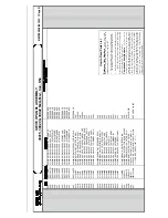
Содержание 30015
Страница 6: ......
Страница 8: ......
Страница 10: ......
Страница 19: ...Section 1 Service and Maintenance ...
Страница 51: ...Section 2 Drive Assemblies ...
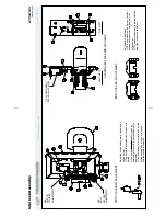
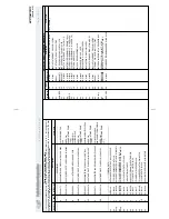
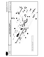
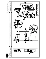
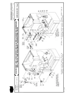
Страница 57: ...BMP920027 93251V Page 1 MOTOR MOUNT ASSEMBLY 30015 30020 30022 RIGID MOUNT WASHER EXTRACTORS DRIVE ASSEMBLIES ...
Страница 59: ...BMP950003 95107V Page 1 MOTOR MOUNT 30015 30020 S4A S4G S4J S4T ...
Страница 68: ......
Страница 69: ...Section 3 Bearing Assemblies ...
Страница 72: ...BMP910032 96141V Page 1 MAIN BEARING ASSEMBLY 30015C4x M4x K5x S5x ...
Страница 74: ...BMP910033 96141V Page 1 MAIN BEARING ASSEMBLY ...
Страница 76: ...BMP910034 95116V Page 1 MAIN BEARING ASSEMBLY 30015M6x ...
Страница 80: ...BMP910035 93251V Page 1 JACKSHAFT ASSEMBLY 30015 30020 30022 RIGID MOUNT WASHER EXTRACTORS ...
Страница 82: ......
Страница 83: ...Section 4 Shell and Door Assemblies ...
Страница 86: ...BMP920009 94491V Page 1 DOOR ASSEMBLY 30015 30020 RIGID MOUNT WASHER EXTRACTORS ...
Страница 90: ......
Страница 91: ...Section 5 Control and Sensing Devices ...
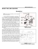
Страница 100: ...BMP920010 97281V Page 1 COIN ASSEMBLY INSTALLATION 240V 30015 30020 30022 COIN MACHINES ...
Страница 105: ...Section 6 Chemical Supply Devices ...
Страница 113: ...Section 7 Water and Steam Piping and Assemblies ...
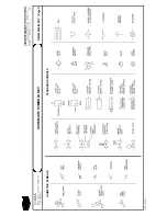
Страница 114: ...ISOMETRIC SYMBOLS STANDARD SYMBOLS BMP920008 93027V Page 1 SCHEMATIC SYMBOLS KEY ...
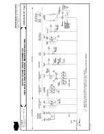
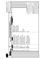
Страница 115: ...BMP920015 96132V Page 1 WATER STEAM DRAIN SCHEMATICS 30015 30020 30022 RIGID MOUNT WASHER EXTRACTORS ...
Страница 132: ...BMP920021 93251V Page 1 STEAM INSTALLATION 30015 30020 30022 RIGID MOUNT WASHER EXTRACTORS ...
Страница 136: ...BMP920020 93251V Page 1 DRAIN VALVE INSTALLATION 30015 30020 30022 RIGID MOUNT WASHER EXTRACTORS ...
Страница 138: ...BMP920017 93251V Page 1 ELECTRIC DRAIN VALVE 30015 30020 30022 RIGID MOUNT WASHER EXTRACTORS ...
Страница 139: ...Section 8 Pneumatic Piping and Assemblies ...


