


OM-708 Page 1
SECTION 1 – SAFETY PRECAUTIONS - READ BEFORE USING
spotom _nd_5/97
1-1.
Symbol Usage
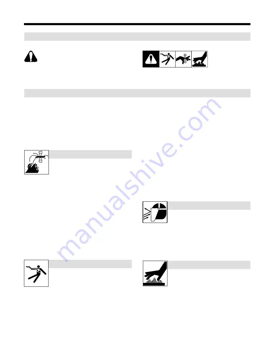
Means Warning! Watch Out! There are possible hazards
with this procedure! The possible hazards are shown in
the adjoining symbols.
Y
Marks a special safety message.
.
Means “Note”; not safety related.
This group of symbols means Warning! Watch Out! possible
ELECTRIC SHOCK, MOVING PARTS, and HOT PARTS hazards.
Consult symbols and related instructions below for necessary actions
to avoid the hazards.
1-2.
Resistance Spot Welding Hazards
Y
The symbols shown below are used throughout this manual to
call attention to and identify possible hazards. When you see
the symbol, watch out, and follow the related instructions to
avoid the hazard. The safety information given below is only
a summary of the more complete safety information found in
the Safety Standards listed in Section NO TAG. Read and fol-
low all Safety Standards.
Y
Only qualified persons should install, operate, maintain, and
repair this unit.
Y
During operation, keep everybody, especially children, away.
SPOT WELDING can cause fire.
Sparks can fly off from the weld. The flying sparks,
hot workpiece, and hot equipment can cause fires,
burns, and explosions.
D
Protect yourself and others from flying sparks and hot metal.
D
Do not spot weld where flying sparks can strike flammable material.
D
Remove all flammables within 35 ft (10.7 m) of the weld. If this is not
possible, tightly cover them with approved covers.
D
Be alert that welding sparks can easily go through small cracks and
openings to adjacent areas.
D
Watch for fire, and keep a fire extinguisher nearby.
D
Do not spot weld on closed containers such as tanks or drums.
D
Do not weld where the atmosphere may contain flammable dust,
gas, or liquid vapors (such as gasoline).
D
Remove any combustibles, such as a butane lighter or matches,
from your person before doing any welding.
D
After completion of work, inspect area to ensure it is free of sparks,
glowing embers, and flames.
D
Do not exceed the equipment rated capacity.
D
Use only correct fuses or circuit breakers. Do not oversize or
bypass them.
Touching live electrical parts can cause fatal shocks
or severe burns. The input power circuit and
machine internal circuits are also live when power is
on. Incorrectly installed or improperly grounded
equipment is a hazard.
ELECTRIC SHOCK can kill.
D
Do not touch live electrical parts.
D
Wear dry, hole-free insulating gloves and body protection.
D
Disconnect input power before installing or servicing this equip-
ment. Lockout/tagout input power according to OSHA 29 CFR
1910.147 (see Safety Standards).
D
Properly install and ground this equipment according to this manual
and national, state, and local codes.
D
Check and be sure that input power cord ground wire is properly
connected to ground terminal in disconnect box or that cord plug is
connected to a properly grounded receptacle outlet – always
double-check the supply ground before applying power.
D
When making input connections, attach the grounding conductor
first – double-check connections.
D
Keep cords dry, free of oil and grease, and protected from hot metal
and sparks.
D
Frequently inspect input power cord and ground conductor for dam-
age or bare wiring – replace immediately if damaged – bare wiring
can kill. Check ground conductor for continuity.
D
Turn off all equipment when not in use.
D
For water-cooled equipment, check and repair or replace any leak-
ing hoses or fittings. Do not use any electrical equipment if you are
wet or in a wet area.
D
Use only well-maintained equipment. Repair or replace damaged
parts at once.
D
Wear a safety harness if working above floor level.
D
Keep all panels, covers, and guards securely in place.
Very often sparks fly off from the joint area.
D
Wear approved face shield or safety goggles
with side shields.
FLYING SPARKS can cause injury.
D
Wear protective garments such as oil-free, flame-resistant leather
gloves, heavy shirt, cuffless trousers, high shoes, and a cap.
Synthetic material usually does not provide such protection.
D
Protect others in nearby areas by using approved flame-resistant or
noncombustible fire curtains or shields. Have all nearby persons
wear safety glasses with side shields.
Wear gloves or allow cooling period before servicing
tongs or tips.
D
Always wear welding-type, insulated gloves
when using this equipment.
HOT METAL can cause burns.
D
Do not touch workpiece, tips, or tongs with bare hands.
D
Allow tongs and tips to cool before touching.
Содержание LMSW-52T
Страница 4: ......
Страница 15: ...OM 708 Page 11 Notes...
Страница 21: ...Notes...
Страница 22: ...Notes...


