


OM-687 Page 2
ST-800 656-A / Ref. S-170 364
1
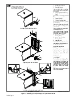
Welding Power Source
2
Mounting Bracket
Use matching holes on welding
power source base to install mount-
ing brackets.
3
Axle (Supplied With Running
Gear)
Install axle to mounting brackets
(2).
4
Support Bracket
5
Cylinder Rack Assembly
Install support bracket to cylinder
rack assembly.
Remove the three screws from the
top rear of the welding power
source cover.
Secure cylinder rack assembly to
mounting brackets (2).
Secure support bracket to welding
power source (1) with screws re-
moved from top rear of cover.
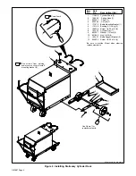
6
Wheel (Supplied With
Running Gear)
7
Washer (Supplied With
Running Gear)
8
Retaining Ring
Install wheels to axle, and secure
with washers and retaining rings.
9
Weld Cable Guide
Install weld cable guides.
10 Spring Hook
Install spring hooks into hole that
will allow chains to be tightened as
tight as possible around gas cylin-
ders. Secure cylinder with chains
as shown.
11 Safety Lock
12 Lift Lever
Push safety lock while turning lift le-
ver to raise or lower cylinder rack.
Keep a tight grip on lever when rais-
ing and lowering rack loaded with a
cylinder as lever is under tension.
Keep body parts out from under
rack while raising and lowering
rack.
See Parts List for hardware sizes
used in this installation.
Connect primary power cord
to welding power source be-
fore installing cylinder rack.
Installing mounting brackets and axle.
Installing cylinder rack and wheels
Installing weld cable guides and spring hooks,
and operating the lift rack.
1
2
3
4
5
6
7
8
9
10
11
12
Figure 2. Installing And Operating The Cylinder Rack/Lift


