background image

OM-232 384 Page 36

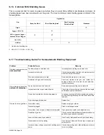
8-16. Common MIG Shielding Gases

This is a general chart for common gases and where they are used. Many different combinations (mixtures) of
shielding gases have been developed over the years. The most commonly used shielding gases are listed in the
following table.

Application

Gas

Spray Arc Steel

Short Circuiting Steel

Short Circuiting

Stainless Steel

 Aluminum

Argon

X

Argon + 25% CO

2

X

80% or  greater Argon +

balance CO

2

 or Oxygen

X

X

1

100% CO

2

X

Tri-Mix2

X

1

Limited short circuiting use

2

90% HE + 7-1/2% AR + 2-1/2% CO

2

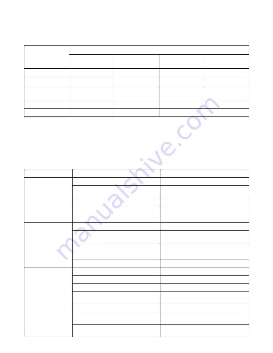
8-17. Troubleshooting Guide For Semiautomatic Welding Equipment

Problem

Probable Cause

Remedy

Wire feed motor operates, but
wire does not feed.

Too little pressure on wire feed rolls.

Increase pressure setting on wire feed rolls.

wire does not feed.

Incorrect wire feed rolls.

Check size stamped on wire feed rolls, replace to match
wire size and type if necessary.

Wire spool brake pressure too high.

Decrease brake pressure on wire spool.

Restriction in the gun and/or assembly.

Check and replace cable, gun, and contact tip if
damaged. Check size of contact tip and cable liner,
replace if necessary.

Wire curling up in front of the
wire feed rolls (bird nesting).

Too much pressure on wire feed rolls.

Decrease pressure setting on wire feed rolls.

wire feed rolls (bird nesting).

Incorrect cable liner or gun contact tip size.

Check size of contact tip and check cable liner length
and diameter, replace if necessary.

Gun end not inserted into drive housing properly.

Loosen gun securing bolt in drive housing and push gun
end into housing just enough so it does not touch wire
feed rolls.

Dirty or damaged (kinked) liner.

Replace liner.

Wire feeds, but no gas flows.

Gas cylinder empty.

Replace empty gas cylinder.

Gas nozzle plugged.

Clean or replace gas nozzle.

Gas cylinder valve not open or flowmeter not adjusted.

Open gas valve at cylinder and adjust flow rate.

Restriction in gas line.

Check gas hose between flowmeter and wire feeder, and
gas hose in gun and cable assembly.

Loose or broken wires to gas solenoid.

Have Factory Authorized Service Agent repair wiring.

Gas solenoid valve not operating.

Have Factory Authorized Service Agent replace gas
solenoid valve.

Incorrect primary voltage connected to welding power
source.

Check primary voltage and relink welding power source
for correct voltage.

Содержание Millermatic 212

Страница 1: ...Processes Description Arc Welding Power Source and Wire Feeder OM 232 384C 2008 01 Visit our website at www MillerWelds com Millermatic 212 R Flux Cored FCAW Welding MIG GMAW Welding File MIG GMAW ...

Страница 2: ...ntinue the tradition They re just as committed to providing equipment and service that meets the high standards of quality and value established in 1929 This Owner s Manual is designed to help you get the most out of your Miller products Please take time to read the Safety precautions They will help you protect yourself against potential hazards on the worksite We ve made installation and operatio...

Страница 3: ...CTION 4 INSTALLATION 11 4 1 Welding Power Source And MIG Gun Specifications 11 4 2 Welding Power Source Duty Cycle And Overheating 12 4 3 Volt Ampere Curves 12 4 4 Connecting To Weld Output Terminals 13 4 5 Installing Work Cable And Clamp 13 4 6 Connecting An Optional Spool Gun 14 4 7 Setting Gun Polarity For Wire Type 14 4 8 Installing Gas Supply 15 4 9 Installing MIG Wire Spool and Adjusting Hub...

Страница 4: ...tics 32 8 7 Good Weld Bead Characteristics 32 8 8 Troubleshooting Excessive Spatter 33 8 9 Troubleshooting Porosity 33 8 10 Troubleshooting Excessive Penetration 33 8 11 Troubleshooting Lack Of Penetration 34 8 12 Troubleshooting Incomplete Fusion 34 8 13 Troubleshooting Burn Through 34 8 14 Troubleshooting Waviness Of Bead 35 8 15 Troubleshooting Distortion 35 8 16 Common MIG Shielding Gases 36 8...

Страница 5: ...n cramped positions such as sitting kneeling or lying or when there is a high risk of unavoid able or accidental contact with the workpiece or ground For these conditions use the following equipment in order presented 1 a semiautomaticDC constant voltage wire welder 2 a DC manual stick welder or 3 an AC welder with reduced open circuit volt age In most situations use of a DC constant voltage wire ...

Страница 6: ...ss they are properly prepared according to AWS F4 1 see Safety Standards D Do not weld where the atmosphere may contain flammable dust gas or liquid vapors such as gasoline D Connect work cable to the work as close to the welding area as practical to prevent welding current from traveling long possibly unknown paths and causing electric shock sparks and fire hazards D Do not use welder to thaw fro...

Страница 7: ...fans D Keep all doors panels covers and guards closed and securely in place D Have only qualified persons remove doors panels covers or guards for maintenance as necessary D Reinstall doors panels covers or guards when maintenance is finished and before reconnecting input power READ INSTRUCTIONS D Read Owner s Manual before using or servic ing unit D Use only genuine replacement parts from the man...

Страница 8: ... York NY 10036 8002 phone 212 642 4900 website www ansi org Standard for Fire Prevention During Welding Cutting and Other Hot Work NFPA Standard 51B from National Fire Protection Association P O Box 9101 Quincy MA 02269 9101 phone 617 770 3000 web site www nfpa org OSHA Occupational Safety and Health Standards for General Indus try Title 29 Code of Federal Regulations CFR Part 1910 Subpart Q and P...

Страница 9: ...urant électrique s avère nécessaire se servir de la fonction de télécommande si l appareil en est équipé D D autres consignes de sécurité sont nécessaires dans les condi tions suivantes risques électriques dans un environnement humideou si l on porte des vêtements mouillés sur des structures métalliquestelles que sols grilles ou échafaudages en position coincée comme assise à genoux ou couchée ou ...

Страница 10: ...es de protection Le soudage effectué sur des conteneurs fermés tels que des réservoirs tambours ou des conduites peu provoquer leur éclatement Des étincelles peuven être projetées de l arc de soudure La projection d étincelles des pièces chaudes et des équipements chauds peut provoquer des incendies e des brûlures Le contact accidentel de l électrode avec des objets métalliquespeut provoquer des é...

Страница 11: ...ur usage ultérieur D Utiliser les équipements corrects les bonnes procédures et suffi samment de personnes pour soulever et déplacer les bouteilles D Lire et suivre les instructions sur les bouteilles de gaz comprimé l équipement connexe et le dépliant P 1 de la CGA Compressed Gas Association mentionné dans les principales normes de sécu rité 2 3 Dangers supplémentaires en relation avec l installa...

Страница 12: ...er des interférences D L énergie électromagnétique risque de provo quer des interférences pour l équipement élec tronique sensible tel que les ordinateurs et l é quipement commandé par ordinateur tel que les robots D Veiller à ce que tout l équipement de la zone de soudage soit compatibleélectromagnétiquement D Pour réduire la possibilité d interférence maintenir les câbles de soudage aussi courts...

Страница 13: ... Pittsburgh PA 15250 7954 téléphone 1 866 512 1800 il y a 10 bureaux régionaux le télépho ne de la région 5 Chicago est 312 353 2220 site Internet www osha gov 2 6 Information EMF Considérationssur le soudage et les effets de basse fréquence et des champs magnétiques et électriques Le courant de soudage pendant son passage dans les câbles de sou dage causera des champs électromagnétiques Il y a eu...

Страница 14: ...OM 232 384 Page 10 ...

Страница 15: ...put at Rated Output 60 Hz Single Phase Rated Output Amperage Range DC Max Open Circuit Voltage DC 200 208 V 230 V KVA KW 160 A at 24 5 VDC 60 Duty Cycle 210 A at 23 VDC 30 Duty Cycle 30 210 34 5 31 2 2 1 27 1 1 8 6 36 0 51 5 45 0 26 While idling Wire Type and Diameter Wire Feed Speed Maximum Spool Size Dimensions Net Weight Without Gun Solid Steel Stainless Steel Flux Cored 50 700 IPM 1 3 17 8 12 ...

Страница 16: ... fan runs Wait fifteen minutes for unit to cool Reduce amperage or voltage or duty cycle before welding NOTICE Exceeding duty cycle can damage unit and void warranty Overheating 0 15 A or V OR Reduce Duty Cycle Minutes duty1 4 95 204 075 30 Duty Cycle At 210 Amperes 60 Duty Cycle At 160 Amperes 3 Minutes Welding 7 Minutes Resting 4 3 Volt Ampere Curves Volt amperecurves show minimum and maximum vo...

Страница 17: ...terminal onto weld output terminal and secure with nut so that weld cable terminal is tight against copper bar Do not place anything between weld cable terminal and copper bar Make sure that the surfaces of the weld cable terminal and copper bar are clean Tools Needed 3 4 in 19 mm 4 2 3 Do not place anything between Correct Installation Incorrect Installation 1 weld cable terminal and copper bar 4...

Страница 18: ... Terminal Connect weld cable from spool gun to positive output terminal Close door 3 2 1 4 804 922 A 4 7 Setting Gun Polarity For Wire Type 1 Polarity Changeover Label Information Always read and follow manufac ture s recommended polarity 1 3 4 11 16 in Ref 190 821 A Changing Polarity D D Wire Drive Assembly Lead Work Clamp Lead Positive Terminal Shown as shipped Electrode Positive DCEP For solid ...

Страница 19: ...stall so face is vertical 5 Regulator Flowmeter Gas Hose Connection 6 Welding Power Source Gas Hose Connection For Spool Gun 7 Welding Power Source Gas Hose Connection For MIG Gun Connect gas hose between regulator flowmetergas hose con nection and fitting on rear of welding power source 8 Gas Flow Adjustment Control Typical flow rate is 25 cfh cubic feet per hour Check wire manufacturer s recomme...

Страница 20: ...to turn spool tension is set 15 16 in Use compression spring with 8 in 200 mm spools Tools Needed 072573 B 802 922 Installing 1 Or 2 lb Wire Spool To install either a 1 lb or 2 lb wire spool follow the procedure as shown in the illustration Remove these components from spindle Spindle Spindle Install these components onto spindle Order extra spring Part No 186 437 ...

Страница 21: ...00 230 Input Amperes At Rated Output 32 28 Max Recommended Standard Fuse Rating In Amperes Circuit Breaker 1 Time Delay 2 35 30 Normal Operating 3 45 40 Min Input Conductor Size In AWG 4 10 10 Max Recommended Input Conductor Length In Feet Meters 89 27 118 36 Min Grounding Conductor Size In AWG 4 10 10 Reference 2005 National Electrical Code NEC including article 630 1 Choose a circuit breaker wit...

Страница 22: ...ct input power 2 Plug NEMA Type 6 50P 3 Receptacle NEMA Type 6 50R Customer Supplied 4 Input Power Cord Connect directly to line disconnect device if hard wiring is required 5 Black And White Input Conductor L1 And L2 6 Green Or Green Yellow Grounding Conductor 7 Disconnect Device switch shown in the OFF position 8 Disconnect Device Grounding Terminal 9 Disconnect Device Line Terminals Connect gre...

Страница 23: ...embly Pull and hold wire cut off end Push wire thru guides into gun continue to hold wire Close and tighten pressure assembly and let go of wire Remove gun nozzle and contact tip Turn On Press gun trigger until wire comes out of gun Reinstall contact tip and nozzle Feed wire to check drive roll pressure Tighten knob enough to prevent slipping Cut off wire Close and latch door Tighten Use pressure ...

Страница 24: ...rameter chart for good starting point Turn control clockwise to increase voltage 2 Wire Speed Control Set Wire Speed control according to the parameterchart Increase or decrease wire speed to obtain desired bead profile and travel speed 3 Over Temp Light If unit overheats light turns on and output stops Allow unit to cool before resuming operation 3 Ref 226 648 C 1 2 ...

Страница 25: ... A complete Parts List is available at www MillerWelds com OM 232 384 Page 21 Notes ...

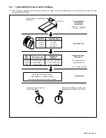
Страница 26: ... Gases And Flow Rate Suggested Wire Types Wire Sizes Diameters 0 023 0 6mm 0 030 0 8mm 0 035 0 9mm 0 023 0 6mm 0 030 0 8mm 0 035 0 9mm STEEL ER70s 6 100 CO 2 75 Ar 25 cfh Ar CO produces less spatter better overall appearance 2 2 Solid or hard ER70s 6 Solid or hard 25 cfh 25 CO STAINLESS STEEL Aluminum with optional Spoolmatet 3035 spoolgun Material STEEL Stainless Steel ER 308 ER 308L ER 308LSi Al...

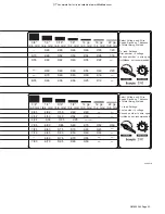
Страница 27: ...s of Metal Being Welded To read Settings First number is voltage Second number is wire speed Means not recommended 5 90 6 90 5 80 7 70 7 80 4 65 4 52 3 8 9 5 mm 6 80 6 65 6 80 6 70 4 62 4 50 1 4 6 4 mm 5 75 5 60 5 75 5 65 3 55 3 40 3 16 4 8 mm 5 80 5 70 4 50 4 70 4 60 2 42 2 32 1 8 3 2 mm 4 75 4 60 3 40 3 55 3 50 2 40 2 30 14 ga 2 0 mm 3 52 3 45 18 ga 1 2 mm 22 ga 0 8 mm Select Voltage and Wire Sp...

Страница 28: ...ect the unit from damage due to overheating If TP1 and or TP2 opens welding output will shut off and the Over Temp light will turn on Wait until Over Temp light turns off before trying to weld 6 3 Changing Drive Roll and Wire Inlet Guide 1 Securing Screw 2 Inlet Wire Guide Loosen screw Slide tip as close to drive rolls as possible without touching Tighten screw 3 Drive Roll The drive roll consists...

Страница 29: ...open overheating Allow fan to run the thermostat will close when the unit has cooled see Section 6 2 No weld output wire feeds Connect work clamp to get good metal to metal contact Replace contact tip see welding gun Owner s Manual Low weld output Connect unit to proper input voltage or check for low line voltage see Section 4 12 Low high or erratic wire speed Readjust front panel settings see Sec...

Страница 30: ...ub tension see Section 4 9 Replace contact tip if blocked see welding gun Owner s Manual Clean or replace wire inlet guide or liner if dirty or plugged see welding gun Owner s Manual Replace drive roll if worn or slipping see Section 6 3 Secure gun plug in receptacle or repair leads or replace trigger switch see welding gun Owner s Manual Check and clear any restrictions at drive assembly and line...

Страница 31: ...OM 232 384 Page 27 SECTION 7 ELECTRICAL DIAGRAM 229 597 B Figure 7 1 Welding Power Source Circuit Diagram ...

Страница 32: ...rkpiece Gun Regulator Flowmeter Gas Shielding Gas Work Clamp 8 1 Typical MIG Process Connections Weld current can damage electronic parts in vehicles Disconnect both battery cables before welding on a vehicle Place work clamp as close to the weld as possible mig1_2007 05 Ref 801 909 A ...

Страница 33: ...parameters 035 in Recommendation Wire Speed Approx 1 8 or 0 125 in 0 001 in 1 ampere 0 125 in 125 A Wire Size Amperage Range 0 023 in 0 030 in 0 035 in Select Wire Size Wire Size 0 023 in 0 030 in 0 035 in 3 5 in per ampere 2 in per ampere 1 6 in per ampere Select Wire Speed Amperage 125 A based on 1 8 in material thickness ipm inches per minute Low voltage wire stubs into work High voltage arc is...

Страница 34: ... in 13 mm past end of nozzle and tip of wire is positioned correctly on seam 1 Hold Gun and Control Gun Trigger 2 Workpiece 3 Work Clamp 4 Electrode Extension Stickout 1 4 to 1 2 in 6 To 13 mm 5 Cradle Gun and Rest Hand on Workpiece 2 3 5 4 90 90 0 15 45 45 1 0 15 S 0421 A End View of Work Angle Side View of Gun Angle GROOVE WELDS End View of Work Angle Side View of Gun Angle FILLET WELDS ...

Страница 35: ... electrode extension stickout travel speed thickness of base metal wire feed speed weld current and voltage Slow FILLET WELD ELECTODE EXTENSIONS STICKOUT ELECTRODE EXTENSIONS STICKOUT GUN ANGLES AND WELD BEAD PROFILES 10 10 GUN TRAVEL SPEED S 0634 Push Perpendicular Drag Short Normal Long Short Normal Long Normal Fast ...

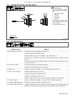
Страница 36: ...nt Along Seam 3 Weave Patterns Use weave patterns to cover a wide area in one pass of the electrode S 0054 A 3 1 2 8 6 Poor Weld Bead Characteristics 1 Large Spatter Deposits 2 Rough Uneven Bead 3 Slight Crater During Welding 4 Bad Overlap 5 Poor Penetration 5 4 2 3 1 S 0053 A 8 7 Good Weld Bead Characteristics 1 Fine Spatter 2 Uniform Bead 3 Moderate Crater During Welding Weld a new bead or layer...

Страница 37: ...s in weld metal S 0635 Possible Causes Corrective Actions Insufficient shielding gas at welding arc Increase flow of shielding gas at regulator flowmeter and or prevent drafts near welding arc Remove spatter from gun nozzle Check gas hoses for leaks Place nozzle 1 4 to 1 2 in 6 13 mm from workpiece Hold gun near bead at end of weld until molten metal solidifies Wrong gas Use welding grade shieldin...

Страница 38: ... welding power source 8 12 Troubleshooting Incomplete Fusion Incomplete Fusion failure of weld metal to fuse completely with base metal or a preceeding weld bead S 0637 Possible Causes Corrective Actions Workpiece dirty Remove all grease oil moisture rust paint undercoating and dirt from work surface before welding Insufficient heat input Select higher voltage range and or adjust wire feed speed I...

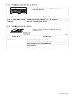
Страница 39: ...Support hand on solid surface or use two hands 8 15 Troubleshooting Distortion Distortion contraction of weld metal during welding that forces base metal to move Base metal moves in the direction of the weld bead S 0642 Possible Causes Corrective Actions Excessive heat input Use restraint clamp to hold base metal in position Make tack welds along joint before starting welding operation Select lowe...

Страница 40: ...maged Check size of contact tip and cable liner replace if necessary Wire curling up in front of the wire feed rolls bird nesting Too much pressure on wire feed rolls Decrease pressure setting on wire feed rolls wire feed rolls bird nesting Incorrect cable liner or gun contact tip size Check size of contact tip and check cable liner length and diameter replace if necessary Gun end not inserted int...

Страница 41: ...necessary Wrong size gun liner or contact tip Match liner and contact tip to wire size and type Incorrect voltage setting for selected wire feed speed on welding power source Readjust welding parameters Loose connections at the gun weld cable or work cable Check and tighten all connections Gun in poor shape or loose connection inside gun Repair or replace gun as necessary ...

Страница 42: ... roll types may be mixed to suit particular requirements example V Knurled roll in combination with U Grooved Ref S 0026 B 7 91 Wire Diameter Fraction Decimal Metric 030 035 in 030 in 035 in 045 in 030 035 in 030 in 035 in 045 in 0 8 0 9 mm 0 8 mm 0 9 mm 1 2 mm Kit No 204 579 079 594 079 595 079 596 Drive Roll Part No Type 203 526 053 695 053 700 053 697 V Grooved V Grooved V Grooved V Grooved Inl...

Страница 43: ...uns and Subarc SAW Guns Induction Heating Coils and Blankets Cables and Non Electronic Controls APT SAF Model Plasma Cutting Torches Remote Controls Accessory Kits Replacement Parts No labor Spoolmate Spoolguns Canvas Covers Miller s True Blue Limited Warranty shall not apply to 1 Consumable components such as contact tips cutting nozzles contactors brushes slip rings relays or parts that fail due...

Страница 44: ...d retain with your personal records Always provide Model Name and Serial Style Number Contact a DISTRIBUTOR or SERVICE AGENCY near you Welding Supplies and Consumables Options and Accessories Personal Safety Equipment Service and Repair Replacement Parts Training Schools Videos Books Technical Manuals Servicing Information and Parts Circuit Diagrams Welding Process Handbooks Contact the Delivering...

Отзывы: