Miller Edge Rband RB-G-K10 Скачать руководство пользователя страница 2

www.milleredge.com        [email protected]        800-220-3343        

2/5

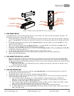
5.  Determine which monitored interface your operator uses:

• 

10K Operator [Table 1]: Connect the 

COM (C1/C2) and the correct output connections (BS1/BS2) to your operator. Set 

DIP switch 4 to off.

• 

N.C. Operator [Table 2]: Connect the 

COM (C1/C2) and the correct output connections (CS1/CS2) to your operator.  The 

A Test terminals must be used for operators requiring N.C. inputs. Set DIP switch 4 to on.

6.  Turn on power to the operator. Note: it takes ~5 seconds for the Receiver to initialize. 

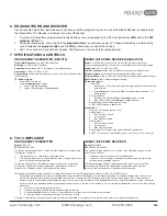
TABLE 1. REMOVABLE CONNECTORS 

ON

1 2 3 4

12/24 AC/DC

CS1 C1 BS1 CS2 C2 BS2 NO3 C3

COM.A TEST

+

-

8-PIN CONNECTOR

Power

+12/24 AC/DC


„ 

Constant power source

-12/24 AC/DC


„ 

Constant power source (ground)

Relay Output 1 

CS1


„ 

N.C. monitored input 

C1


„ 

Monitored input Common 

BS1


„ 

10K monitored input 

Relay Output 2

CS2


„ 

N.C. monitored input

C2


„ 

Monitored input Common

BS2


„ 

10K monitored input

4-PIN CONNECTOR

Relay Output 3

NO3


„ 

Low battery alarm (optional)

C3


„ 

Low battery alarm (optional)

N.C. Power Cycling

COM


„ 

COM: Switched power Common 

A TEST


„ 

+12/24VDC: Switched power source

TABLE 2. NORMALLY CLOSED OPERATORS: Removable Connector Assignments by Manufacturer

HySecurity

ON

1 2 3 4

DIP Switch #4

• O

n

 to run

• 

Off

 to test

CS1 C1 BS1 CS2 C2 BS2 NO3 C3

COM. A TEST

12/24 AC/DC

+

-

SENSOR COMMON

COMMON (not sensor common)

24 VDC

S1

S2

Ramset


ON

DIP Switch #4

• 

Turn to 

o

n

CS1 C1 BS1 CS2 C2 BS2 NO3 C3

COM.A TEST

12/24 AC/DC

+

-

24 VAC on terminal strip

NC 

(JP13, PIN 1)

COM 

(JP13, PIN 3)

VS 

(JP13, PIN 5)

1 2 3 4

VS 

(JP13, PIN 4)

All-O-Matic

ON

DIP Switch #4

• 

Turn to 

o

n

CS1 C1 BS1 CS2 C2 BS2 NO3 C3

COM.A TEST

12/24 AC/DC

+

-

+12 or 24 

VDC

GR

OUND

MON_CLOSE

COMMON

MON_OPEN

COMMON

COMMON

MON-12 VDC

1 2 3 4

Maximum Controls

CS1 C1 BS1 CS2 C2 BS2 NO3 C3

COM.A TEST

12/24 AC/DC

+

-

12 or 24 

VDC*

GND*

EDGE 1**

GND**

EDGE 2**

GND**

GND**

+12 VDC**

ON

1 2 3 4

DIP Switch #4

• 

Turn to 

o

n

NOTE

For operator software at these versions 
or higher, leave 

DIP switch 4 in the on 

position:
•  Smart Touch Controllers (STC): h4.56
•  Smat DC Controllers (SDC): h5.57
•  S.T.A.R.T.: v3.03

Содержание Rband RB-G-K10

Страница 1: ... Edge Transmitter RB TX10 RBand Gate Edge Receiver RB G RX10 Receiver antenna 2 3 6V AA lithium batteries 4 6 pan head transmitter mounting screws RB TX10 Contents RBand Gate Edge Transmitter RB TX10 2 3 6V AA lithium batteries 4 6 pan head transmitter mounting screws Replacement 3 6V AA lithium batteries can be purchased at your local electronics store or via Miller Edge Required 1 8 flat blade s...

Страница 2: ...4 PIN CONNECTOR Relay Output 3 NO3 Low battery alarm optional C3 Low battery alarm optional N C Power Cycling COM COM Switched power Common A TEST 12 24VDC Switched power source TABLE 2 NORMALLY CLOSED OPERATORS Removable Connector Assignments by Manufacturer HySecurity ON 1 2 3 4 DIP Switch 4 On to run Off to test CS1 C1 BS1 CS2 C2 BS2 NO3 C3 COM ATEST 12 24 AC DC SENSOR COMMON COMMON not sensor ...

Страница 3: ...s DIP SWITCH SETTINGS ON 1 2 3 4 Switch 1 3 Leave switches in factory default settings Switch 4 Used to enable Normally Closed cycle testing 10K Operator Set to off N C Operator Set to on and connect the switched power to the A Test and Common pins shown above TABLE 2 GND ANT R2 R1 R3 A TEST CHECK PROG ON 1 2 3 4 12 24 AC DC CS1 C1 BS1 CS2 C2 BS2 NO3 C3 COM ATEST MR PROGRAM BUTTON CHECK LED BUTTON...

Страница 4: ...f outer covering of sensing edge cable then feed through the Transmitter strain relief fitting Connect the two sensing edge wires to the removable terminal Dress the wires with a small service loop and tighten the strain relief Mount unit utilizing the mounting holes at the 4 corners of the Transmitter box Affix lid to the Transmitter noting the alignment pin IMAGE 3 Note Altering the NEMA 4 Trans...

Страница 5: ...10K termination Relay Output 3 2 Relay closes when low battery is detected A TEST 2 Connect to switched DC power and Com for N C monitoring 8 FCC COMPLIANCE RBAND EDGE TRANSMITTER Model RB TX10 FCC ID U5Z RB TX10 This device complies with Part 15 of the FCC rules Operation is subject to the following two conditions 1 This device may not cause harmful interference and 2 This device must accept any ...

Отзывы: