Millenium MRO-35 Скачать руководство пользователя страница 7

7

B.  Tools Recommended for Installation 

  The following tools will cover most of the 

installation sites encountered:
1. 

3

/

8

" variable speed electric drill.

2.  Extension work light with outlet.
3.  Safety glasses.
4.  1¼" porcelain hole cutter kit.
5.  1¼" Greenlee hole punch and 

1

/

8

" and 

½" metal drill bits for pilot hole. 

6.  Center punch and hammer.
7.  1¼" wood bit.
8.  Concrete drill bits.
9.  Assorted wood and metal drill bits including 


7

/

32

" metal drill bit. 

10. Phillips head and flat blade screwdrivers.
11. ½", 

9

/

16

" and 

5

/

8

" open end wrenches.

12. 10" Crescent wrench with jaws taped to hold 

faucet. 

13. Basin wrench or 10" pipe wrench.
14. Teflon tape. 
15. Wide masking tape or duct tape. 
16. Plastic tubing cutter. 
17. Extra plastic tubing.
18. Low range air pressure gauge. 
19. Bicycle hand air pump. 
20. Small bottle of liquid chlorine bleach. 
21. Graduated measuring cylinder. 
22. Paper towels, wisk broom and assorted clean 

up materials.

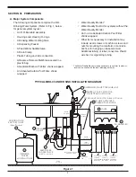
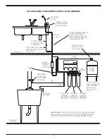
C.  Site Selection for Major System Components 

  The R.O. System was designed to fit under a 

sink, however, because of space limitations 

or other reasons, the system’s flexible design 

allows for other locations. When determining the 

location remember that access to a cold water 

tap line, the household drain, and ease of filter 

replacement are important considerations. 

  All components and tubing should be located in 

an area not exposed to freezing temperatures. If 

winter temperatures are severe, the area should 

be above the minimum temperature listed in 

Table B for proper performance. Do not expose 

unit or tubing to direct sunlight. 

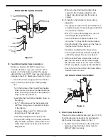
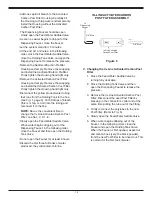
1.  Dispensing Faucet–

The faucet should be 

placed near the sink where drinking water 

is normally obtained. Convenience of use 

(filling of water pitchers and glasses), and an 

open area beneath the faucet under the sink 

for attaching product and drain tubing are 

considerations. A 2" diameter flat surface is 

required above and below the installation site. 

The thickness of the mounting surface should 

not exceed 1¼". Watch for strengthening 

webbing on the underside of cast iron sinks. 

2.  Drinking Water Holding Tank–

The Holding 

Tank may be placed where it is convenient 

within 10 feet of the faucet; under the sink or 

in an adjacent cabinet are best the choices. 

If a longer run of tubing is required, the 

tubing should be the 

3

/

8

" diameter OD size 

to prevent a high pressure drop. Remember, 

these tanks can weigh up to 30 pounds when 

full of water; a firm, level area is required. 

3.  R.O. Manifold Assembly–

The manifold can 

be installed on either the right or left side 

of the under–sink area or a cabinet. The 

right side is recommended because all the 

tubing will be to the back of the cabinet and 

out of the way. Installation in the basement 

is also an option; one location is near the 

laundry/utility sink where cold potable water 

and drain access are handy. The mounting 

location should allow adequate clearance 

and accessibility for cartridge changes. 

4.  Feed Water Connection–

The Feed Water 

Saddle Valve should be located as close to 

the manifold assembly as possible. USE A 

POTABLE COLD WATER SUPPLY ONLY. 

Softened water is preferred as it will extend 

the life of the R.O. Membrane.

5.  Drain Connection–

The waste water must 

go to drain through an anti–siphon air gap. 

The air gap is provided for in the base of 

the faucet. If discharging into a utility sink 

or standpipe, an air gap of greater than 1" 

above the flood rim must be provided. 

  Do NOT connect the system drain line to 

the dishwasher drain or near the garbage 

disposal. Backpressure from these units may 

cause the air gap to overflow.

Содержание MRO-35

Страница 1: ... by NSF International against NSF ANSI Standard 58 for the reduction of the claims specified on the Performance Data Sheet Millennium Reverse Osmosis Drinking Water System Model MRO 35 INSTALLATION OPERATION SERVICE MANUAL ...

Страница 2: ...ertains to people with HIV AIDS patients receiving treatment for cancer recipients of organ or bone marrow transplants transplant patients taking immunosuppressive drugs and persons who have congenital immunodeficiencies The EPA has stated that they do not know the significance of drinking water compared to other possible sources of Cryptosporidium to determine how most people become infected The ...

Страница 3: ...er supply to prevent excess reject water from going to drain when the unit is not producing water WATER QUALITY MONITOR The optional Water Quality Monitor has been integrated into the faucet base for instant monitoring at the touch of a button The monitor compares the level of the Total Dissolved Solids in the incoming feed water versus the product water and calculates the percent rejection The mo...

Страница 4: ...that is available to the user as reverse osmosis treated water when the system is operated without a storage tank or when the storage tank is bypassed Efficiency rating means the percentage of the influent water to the system that is available to the user as reverse osmosis treated water under operating conditions that approximate typical daily usage This reverse osmosis system contains a replacea...

Страница 5: ...e screws and nuts for mounting the manifold or concrete anchors for hanging on basement wall Additional tubing or tube connectors Plastic wire ties for organizing tubing TYPICAL mro 35 UNDER SINK INSTALLATION DIAGRAM Figure 1 The Water Quality Monitor may be necessary to conform to state or local codes check with the local plumbing authority Dispensing Faucet with Air gap drain clamp drain 3 8 Bla...

Страница 6: ... POST filter housing Reverse osmosis membrane housing sediment CARBON prefilter housing BASEMENT FLOOR please note if air gap in faucet is not used in basement installations a proper air gap must be created please check with local plumbing codes see example above FLOOR FEED water saddle valve cold water line only INLET 1 4 Red DRAIN 1 4 Black 1 air gap required POLYTUBE TEE IN LINE ACTIVATED CARBO...

Страница 7: ...ing of water pitchers and glasses and an open area beneath the faucet under the sink for attaching product and drain tubing are considerations A 2 diameter flat surface is required above and below the installation site The thickness of the mounting surface should not exceed 1 Watch for strengthening webbing on the underside of cast iron sinks 2 Drinking Water Holding Tank The Holding Tank may be p...

Страница 8: ...ps Install the punch and tighten the nut to cut the hole Deburr any sharp edges 2b Drilling a porcelain sink It is best to use a special 1 diameter cutter designed for porcelain A carbide tipped masonry bit is a second choice Place a piece of tape over the area to be drilled to help prevent chipping Drill a pilot hole for the porcelain cutter Use the pilot drill supplied with the kit or a carbide ...

Страница 9: ...CK 3 8 POLYTUBE TO DRAIN CLAMP BLACK 1 4 POLYTUBE TO DRAIN PORT ON RO SYSTEM BLUE 3 8 POLYTUBE PRODUCT OUTLET 6 Connect the tubing to the Faucet Push the Blue 3 8 Polytube into the 3 8 Quick Connect Fitting Push the Black 3 8 Polytube onto the large Hose Barb Push the Black Polytube onto the small Hose Barb 7 Determine which direction the handle should face right or left With the handle facing the...

Страница 10: ... When you feel the Valve Handle firmly seated in the clockwise direction the copper tube is pierced and the valve is closed 2b To install on hard steel or brass tubing supply line The supply line should now be drained Use a battery powered or properly grounded drill to avoid shock hazard Drill a 3 16 hole in the supply line do not drill through the opposite wall Turn the handle to expose the lance...

Страница 11: ...ld and insert the tubing Reference the special supplement sheet in the carton for proper connection of all tubing and removal of plugs Run the tubing along its course to the Feed Water Saddle Valve trim to length Refer to Fig 1 Refer to Fig 3 To the end of the red polytube install the Compression Nut the Plastic Ferrule and the Insert Connect to the Feed Water Saddle Valve 3 Locate the Black Drain...

Страница 12: ...ly tighten the Housing hand tight only Remove the plugs labelled MEMBRANE and ACTIVATED CARBON from the underside of the manifold To each of the remaining white Housings add one capful of bleach Insert a Housing O ring engage and firmly tighten the Housings hand tight only Slowly open the Feed Water Saddle Valve turning counter clockwise As soon as the water begins to come out of the Dispensing Fa...

Страница 13: ...n used daily After periods of non use such as a week of vacation it is better to empty the Holding Tank and allow the system to produce fresh water for use If the system is not used for 3 4 weeks or longer it is a good idea to resanitize the system and to change the prefilter and post filters B Changing Filters THIS R O SYSTEM CONTAINS FILTERS WHICH MUST BE REPLACED AT REGULAR INTERVALS TO MAINTAI...

Страница 14: ...t time to change the In Line Activated Carbon Post Filter see Sec V C 1 6 Slowly open the Feed Water Saddle Valve When water begins dripping out of the Dispensing Faucet in the following order close the Faucet and then open the Holding Tank Valve Do not open the Faucet for at least 8 hours Discard the first three full tanks of water produced they will contain chlorine IN LINE ACTIVATED CARBON POST...

Страница 15: ...15 NOTES ...

Страница 16: ...ee check The ASO Valve is malfunctioning Replace ASO Valve components Low pressure at the Dispensing Faucet In Line Activated Carbon Post Filter is plugged Replace Post Filter Air precharge in the Holding Tank is too low Empty water from Holding Tank and with the faucet open adjust the air pressure to 5 7 psig 35 48 kPa range Check for leakage at the Air Valve Stem Holding Tank Valve is partially ...

Страница 17: ...umbing Dissolved gasses in the Feed Water Pretreat Feed Water to remove dissolved gasses Increase in Product Water TDS See high TDS in the Product Water section Drain Water overflows at the Dispensing Faucet Air Gap is blocked Clear Air Gap Rinse with vinegar for removal of calcium buildup Drain tubing is clogged Clear tubing Drain Clamp hole is misaligned Align with hole in the drain pipe Excessi...

Страница 18: ...18 MADE IN USA Exploded View Parts List 19 15 1 2 3 4 5 6 7 8 9 10 11 12 13 14 18 16 17 21 Nitrate Nitrite Test Kit 22 Water Quality Test Kit for systems without the Water Quality Monitor ...

Страница 19: ...3010 Housing 15 R7078 Optional Water Quality Monitor w Probes and Cover 16 S2116 5 Drain Restrictor 50 GPD 189 lpd Green 17 S7125 Activated Carbon Post Filter 18 S1405 1 4 3 8 Fitting Wrench 19 S3072 Wrench for Housing 20 S7206W JG In Line Activated Carbon Post Filter shown on pg 6 R2118 Water Quality Monitor 25 Ft Extension Cable 21 S1447 Nitrate Nitrite Test Kit 22 S1580 Water Quality Test Kit O...

Страница 20: ...so pay for shipping or travel charges to return the defective part s What Does This Warranty Not Cover This warranty does not cover the disposable sediment and carbon filters whose service life depends on feed water conditions In addition the membrane is only warranted if the required feed water conditions are met The above warranty will also not apply to any part of the Millennium R O Drinking Wa...

Отзывы: