background image

OPERATION

16

 TECHNICAL  DOCUMENTATION

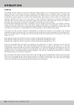
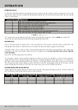
OPERATING STATUS

To alter the operating mode or requested set point, press the button briefly and the setting will cycle to the 

next option. Once you have achieved the required setting the unit will automatically adopt the new setting 

shown on the display.

[1] 

To achieve the requested set point the primary temperature supplied to the unit 

MUST

 be at least 5°C 

above the set point measured at the primary temperature sensor TT4.

MAINTENANCE

Due to the high quality material used in the manufacture of this product and the simple construction the 

Rapide Extreme needs no maintenance and enables an exceptionally long guarantee period. 

Included in the unit is a service valve on the loading pipe from the base of the cylinder to the plate heat 

exchanger, this may only be used when the unit is no longer active. 

Do not close the service valve whilst the 

unit is operating. 

Inspection and cleaning inside the cylinder.

It is possible to clean out the cylinder using fresh mains cold water if so desired. To carry out this operation, 

isolate and disconnect all water supplies and ensure all electrical supplies are isolated. Run a drain hose from 

the drain valve to an operating drain, then connect a controlled mains cold water supply to the unit. Drain 

the unit fully and then slowly supply water to the unit at the rate of drainage. Carry on at this rate until the 

water running from the bottom of the unit runs clear; then carry out two full fills and drains.   

▲ 

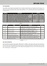
FIGURE 12.

 OPERATIONS STATUS

DESCRIPTION

The unit is off and will not attempt to load

The unit is loading the cylinder to the requested set point

The unit has achieved the requested set point

Unit requested set point is set to 60°C

[1]

Unit requested set point is set to 65°C

[1]

Unit requested set point is set to 70°C

[1]

The unit is loading the cylinder to the anti-legionella set point

The unit has achieved the anti-legionella set point

OPERATING STATUS

oF

nL

nR

n1

n2

n3

hL

hR

RECOMMENDED PERIODIC INSPECTION


MAXIMUM RECOMMENED

DHW TEMP (°C)

WATER HARDNESS

 (°dH)

MAXIMUM RECOMMENDED

PRIMARY TEMP (°C)

RECOMMENDED INTERVAL

FOR CLEANING (MONTHS)

4 - 6

6 - 8

8 - 12

>12

75

70

65

60

90

85

85

70

120

91

72

12

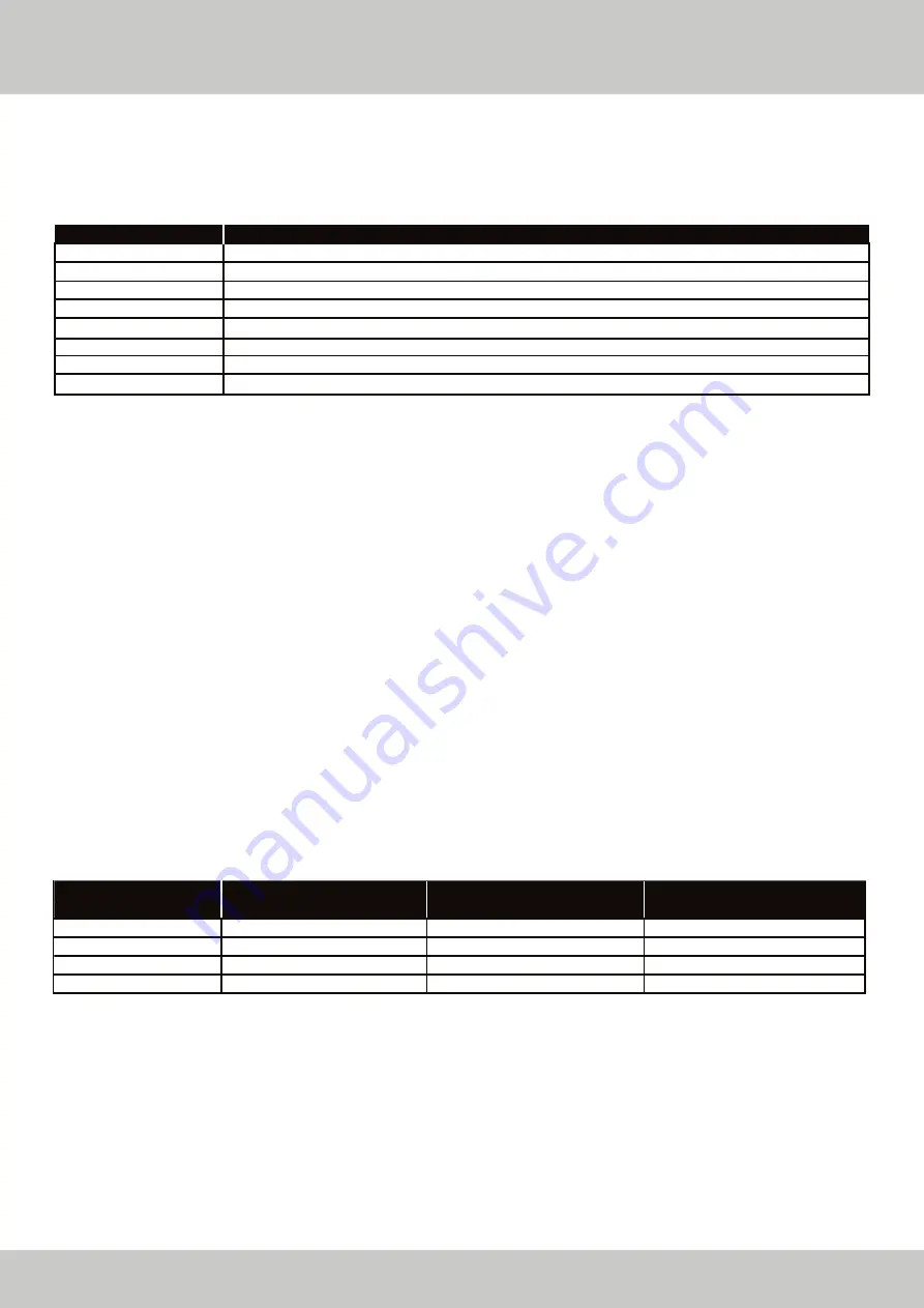
Depending on the water hardness the interval for periodic cleaning will change as below, and the maximum

recommended water temperatures will also alter as below.

Содержание Extreme 200

Страница 1: ...I G H E F F I C I E N C Y H O T W A T E R S Y S T E M S I N S P I R E D E F F I C I E N C Y EXTREME HIGH EFFICIENCY HOT WATER SYSTEMS with INJECTION DYNAMICS TECHNICAL DOCUMENTATION ISSUE 01 18 Rev 0...

Страница 2: ......

Страница 3: ...d Overview Description Operation Operation Installation Siting Over Heat Protection Open Vented Applications Discharge Pipework Discharge Pipework continued Unvented Mains Kit Valve Multiple Rapide Ex...

Страница 4: ...P mm mm BSP kW W V Hz A mm mm mm mm mm mm mm mm mm MJ MJ kWh GENERAL Model Water Content of Appliance Weight Empty DHW Flow Connection DHW Return Connection Primary Flow Connection Primary Return Conn...

Страница 5: ...0 1750 1800 1850 1900 1950 2000 2050 2100 2150 2250 2300 2350 2400 2450 2500 2550 2600 Rapide Extreme 200 Rapide Extreme 300 Rapide Extreme 500 Heat Input kW DHWS Flow litres FLOW CHARACTERISTICS TECH...

Страница 6: ...110 120 5 10 15 20 25 30 35 40 45 50 0 1 0 2 0 3 0 4 0 5 0 6 0 7 0 8 0 9 1 0 0 0 30 Flow Rate Resistance Flow Rate l s Resistance kPa kW Rating Input FLOW CHARACTERISTICS 06 TECHNICAL DOCUMENTATION F...

Страница 7: ...within the vessel to transfer heat the loading system introduces water at 60 C in to the top of the vessel This drastically reduces the proliferation of Legionella bacilli and in instances where the a...

Страница 8: ...ylinder the primary temperature sensor TT4 will look for a minimum primary temperature before releasing the loading pump to allow the loading process to begin The minimum required primary temperature...

Страница 9: ...ted to the primary flow or return pipework to the cylinder as part of the over heat protection for the cylinder to comply with G3 regulations See wiring diagram for electrical connection information P...

Страница 10: ...gh level e g in to a metal hopper and metal downpipe with the end of the discharge clearly visible tundish visible or not or on to a roof capable of withstanding high temperature discharges of water a...

Страница 11: ...2 from a G1 2 temperature relief valve is 9 0m Subtract the resistance for 4 no 22mm elbows at 0 8m each 3 2m Therefore the permitted length equates to 5 8m 5 8m is less than the actual length of 7 0m...

Страница 12: ...fety Valve a tee piece can be fitted between the Pressure Regulating Valve and the non return valve if a balanced cold water tapping is required Expansion Vessel Tapping Mains cold water outlet Non re...

Страница 13: ...ION The Rapide Extreme hot water cylinders can be installed in a multiple arrangement but all pipework must be installed in a parallel fashion or the flow must be arranged to be equal to all cylinders...

Страница 14: ...C D E F Connections 2 and 3 External Legionella Circuit 1 Connections 4 and 5 N A Connections 6 and 7 N A Connections N and L Incoming Electrical Supply 2 Connections 8 and 9 Two Port Valve Supply 2 3...

Страница 15: ...Connection End Switch Common Connection FIGURE 11 SCHEMATIC INSTALLATION DETAIL FOR TWO PORT VALVE HEAT SOURCE TWO PORT VALVE LOADING PUMP DHW FLOW MCW SUPPLY DHW SECONDARY RETURN TT 4 TT 2 TT 3 TT 1...

Страница 16: ...and disconnect all water supplies and ensure all electrical supplies are isolated Run a drain hose from the drain valve to an operating drain then connect a controlled mains cold water supply to the...

Страница 17: ...TT3 loading will continue Check sensor connection at sensor and PCB Loading process continues at 100 Check sensor connection at sensor and PCB Loading process begins after preset time Loading pump is...

Страница 18: ...NOTES 18 TECHNICAL DOCUMENTATION...

Страница 19: ......

Страница 20: ...Systems Ltd 11 Merse Road North Moons Moat Redditch Worcestershire B98 9HL UK North Moons Moat Redditch Worcestershire B98 9HL UK T 44 0 3452 60 60 20 F 44 0 3452 60 60 21 E info mikrofill com www mik...

Отзывы: