D
AT
A BUS
TOP VIEW
DS1820
GND
VCC
DQ
VCC-MCU
J11
RA4
RE2
TS1
R2
1K
VCC
GND
DQ
1 2 3
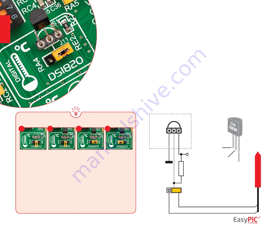
DS1820 - Digital
Temperature Sensor
DS1820 is a digital tempera-
ture sensor that uses
1-wire®
interface
for it’s operation. It is
capable of measuring temperatures
within the range of -55 to 128°C,
and provides ±0.5°C accuracy for
temperatures within the range of -10 to
85°C. It requires 3V to 5.5V power supply
for stable operation. It takes maximum
of 750ms for the DS1820 to calculate
temperature with 9-bit resolution.
1-wire® serial communication
ena-
bles data to be transfered over a single
communication line, while the process
itself is under the control of the master
microcontroller. The advantage of
such communication is that only one
microcontroller pin is used. Multiple
sensors can be connected on the same
line. All slave devices by default have
a unique ID code, which enables the
master device to easily identify all
devices sharing the same interface.
EasyPIC
™
v7 provides a separate socket
(
TS1
) for the DS1820. Communication
line with the microcontroller is selected
with jumper
J11
.
EasyPIC
™
v7 enables you to establish 1-wire® communication between
DS1820
and the microcontroller via
RA4
or
RE2
microcontroller pins. The selection of either
of those two lines is done using
J11
jumper. When placing the sensor in the socket
make sure that half-circle on the board’s silkscreen markings matches the rounded
part of the DS1820 sensor. If you accidently connect the sensor the other way, it
may be permanently damaged and you might need to replace it with another one.
During the readings of the sensor, make sure that no other device (except those in
1-wire network) uses the selected line, because it may interfere with the data.
Figure 15-1:
DS1820 not
connected
Figure 15-2:
DS1820
placed in
socket
Figure 15-3:
DS1820
connected
to RE2 pin
Figure 15-4:
DS1820
connected
to RA4 pin
Figure 15-5:
DS1820
connected
to RE2 pin
Enabling DS1820 Sensor
1
2
3
4
page 28
modules


