


6
BIGdsPIC6 Development System
MikroElektronika
page
&RQQHFWLQJWKH6\VWHPWRD3&
6WHS
Follow the instructions provided in the relevant manuals and install the
dsPICFLASH
program and USB driver from the product CD.
USB drivers are essential for the proper operation of the on-board programmer.
In case you already have one of the Mikroelektronika’s dsPIC compilers installed on your PC, there is no need to reinstall USB drivers
as they are already installed along with the compiler.
6WHS
Use the USB cable to connect the development system to a PC. One end of the USB cable, with a USB connector of B type, should
be connected to the development system, as shown in Figure 1-2, whereas the other end of the cable with a USB connector of A type
should be connected to a PC. When establishing a connection, make sure that jumper J11 is placed in the USB position as shown in
Figure 1-1.
6WHS
Turn on your development system by setting the POWER SUPPLY switch to the ON position. Two LEDs marked as POWER and USB
LINK will be automatically turned on indicating that your development system is ready to use. Use the on-board programmer and the
dsPICFLASH
program to dump a hex code into the microcontroller and employ the system to test and develop your projects.
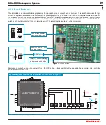
127(
If some additional modules are used, such as LCD, GLCD etc, it is necessary to place them properly on the development
V\VWHPZKLOHLWLVWXUQHGRII2WKHUZLVHHLWKHUFDQEHSHUPDQHQWO\GDPDJHG5HIHUWR¿JXUHEHORZIRUWKHSURSHUSODFLQJRI
the additional modules.
)LJXUH
: Connecting USB cable
1
2
)LJXUH
Power supply
)LJXUH
Placing additional modules on the board
J11 power
supply selector
AC/DC connector
USB connector
POWER SUPPLY switch


