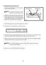
4-4.
4-5.
4-6.
4-7.
4-8.
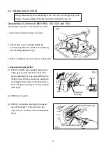
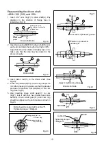
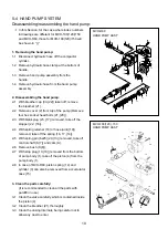
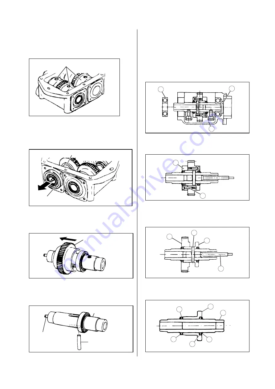
Remove seal cap(27).
Remove pendulums(19, 20) from each pendu-
lum shaft(See Fig.4)
Shift the pendulum(driven shaft side)(4) to one
side of the vibrator case(1) and remove
bearing(2) using the pulley puller, before
removing the pendulum assembly from the
vibrator case(See Fig.5).
Push out the stop ring(5) and gear(driven shaft
side) to one side and pull it out. If the gear is
hard to remove, use the press rather than
tapping on it with hammer.(See Fig.6)
Push the knock pin(12), with your finger or by
using a plastic hammer if it is sticky, which will
allow to pull out piston rod(11) from the pendu-
lum shaft(See Fig.7).
<MVH-R60>
4-4.
4-5.
4-6.
4-7.
4-8.
4-9.
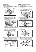
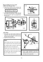
Remove seal cap(25).
Remove pendulums(18) from each pendulum
shaft(See Fig.8)
With the driven shaft assembly pushed out to
the side opposite to pulley and the bearing(2)
taken out, remove the driven shaft assembly
from the vibrator case(See Fig.8).
Disassembling the driven shaft:
Remove four mounting bolts(10) and take out
bearing holder(8)(See Fig.9).
Remove four mounting bolts(44) and driven
gear(31).Tap on and remove parallel pin(12)
before pulling out piston rod(11) from driven
shaft(4)(See Fig.10).
With two contraction stop rings(5) removed,
remove 210
o
cam ring(7) from driven shaft(4)
before removing bearing(9) as well(See Fig.11).
<MVH-100 (120) AND 150>
Pendulum shaft (driven shaft side)
Bearing
Fig.5
Fig.6
Fig.7
Gear
Pendulum shaft
(driven)
Piston rod
Knock pin
The side opposite to pulley
Driven shaft
2
8
7
7
9
9
5
5
4
25
18
10
11
31
12
Fig.8
Fig.9
Fig.10
Fig.11
Pendulums
Fig.4
11
Содержание MVH-R100
Страница 1: ...410 00801 MVH R60 100 120 150 SERVICE MANUAL REVERSIBLE SOIL COMPACTOR R...
Страница 32: ......


