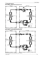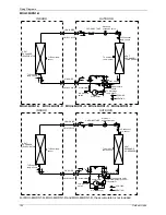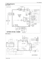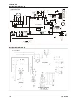
Location selection
Installation
135
2. Location selection
2.1 Indoor unit location selection
The place shall easily support the indoor unit’s weight.
The place can ensure the indoor unit installation and inspection.
The place can ensure the indoor unit horizontally installed.
The place shall allow easy water drainage.
The place shall easily connect with the outdoor unit.
The place where air circulation in the room should be good.
There should not be any heat source or steam near the unit.
There should not be any oil gas near the unit
There should not be any corrosive gas near the unit
There should not be any salty air neat the unit
There should not be strong electromagnetic wave near the unit
There should not be inflammable materials or gas near the unit
There should not be strong voltage vibration.
2.2 Outdoor unit location selection
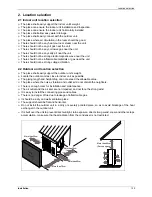
The place shall easily support the outdoor unit’s weight.
Locate the outdoor unit as close to indoor unit as possible
The piping length and height drop can not exceed the allowable value.
The place where the noise, vibration and outlet air do not disturb the neighbors.
There is enough room for installation and maintenance.
The air outlet and the air inlet are not impeded, and not face the strong wind.
It is easy to install the connecting pipes and cables.
There is no danger of fire due to leakage of inflammable gas.
It should be a dry and well ventilation place
The support should be flat and horizontal
Do not install the outdoor unit in a dirty or severely polluted place, so as to avoid blockage of the heat
exchanger in the outdoor unit.
If is built over the unit to prevent direct sunlight, rain exposure, direct strong wend, snow and other scraps
accumulation, make sure that heat radiation from the condenser is not restricted.
More than 30cm
More than 60cm
More than 70cm
More than 30cm
More than 60cm
(Service space
︶
Fenc
e or
obsta
cles
Содержание mcd-24hrdn1
Страница 1: ...DC INVERTER SERIES Service Manual 2013 LIS B 1306...
Страница 2: ......
Страница 4: ......
Страница 15: ...Dimensions 11 2 Dimensions...
Страница 16: ...Service Space 12 3 Service Space...
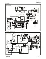
Страница 17: ...Wiring Diagrams 13 4 Wiring Diagrams MCA2 12HRDN1 Q MCA2 18HRDN1 Q...
Страница 21: ...Field Wiring 17 10 Field Wiring MCA2 12HRDN1 Q MCA2 18HRDN1 Q...
Страница 22: ...Field Wiring 18 MCA2 12HRDN1 Q MCA2 18HRDN1 Q...
Страница 28: ...Service Space 26 Four way Cassette Type 3 Service Space 1000mm 1000mm 1000mm 1000m m...
Страница 29: ...Wiring Diagrams Four way Cassette Type 27 4 Wiring Diagrams MCC 24HRDN1 Q MCC 30HRDN1 Q...
Страница 30: ......
Страница 31: ...Wiring Diagrams Four way Cassette Type 21 MCC 36HRDN1 Q MCC 48HRDN1 Q MCC 60HRDN1 R...
Страница 36: ...Field Wiring 26 Four way Cassette Type 10 Field Wiring Wiring chart...
Страница 42: ...Dimensions 32 Super Slim Cassette Type 2 Dimensions Model A H 18 30 205 235 36 48 245 275 60 287 312...
Страница 43: ...Service Space Super Slim Cassette Type 33 3 Service Space 1000mm 1000mm 1000mm 1000m m...
Страница 57: ...Wiring Diagrams Duct Type 47 4 Wiring Diagrams MTB1 12HWDN1 Q MTB 18HWDN1 Q MTB 24HWDN1 Q MTB 30HWDN1 Q...
Страница 58: ...Wiring Diagrams 48 Duct Type MTB 36HWDN1 Q MTB 48HWDN1 Q MTB 60HWDN1 R...
Страница 65: ...Field Wiring Duct Type 55 10 Field Wiring...
Страница 66: ...Field Wiring 56 Duct Type Air conditioner link circuit For model 12 For model 18 60...
Страница 71: ...Service Space Ceiling Floor Type 61 3 Service Space C 35mm 35mm 35mm 1000mm 4 Wiring Diagrams MUB 12HRDN1 Q...
Страница 72: ...Wiring Diagrams 62 Ceiling Floor Type MUB 18HRDN1 Q MUB 24HRDN1 Q MUB 30HRDN1 Q...
Страница 79: ...Field Wiring Ceiling Floor Type 69 10 Field Wiring...
Страница 80: ...Field Wiring 70 Ceiling Floor Type For model 12 For model 18 60...
Страница 82: ......
Страница 85: ...Features Console Type 75...
Страница 86: ...Dimensions 76 Console Type 2 Dimensions MFA 12HRDN1 Q MFA 18HRDN1 Q...
Страница 87: ...Service Space Console Type 77 3 Service Space...
Страница 88: ...Wiring Diagrams 78 Console Type 4 Wiring Diagrams MFA 12HRDN1 Q MFA 18HRDN1 Q...
Страница 93: ...Field Wiring Console Type 83 10 Field Wiring...
Страница 94: ...Field Wiring 84 Console Type...
Страница 97: ...Dimensions High Static Pressure Duct 87 2 Dimensions MHD 36HRDN1 Q MHD 48HRDN1 Q MHD 60HRDN1 R...
Страница 99: ...Wiring Diagrams High Static Pressure Duct 89 4 Wiring Diagrams MHD 36HRDN1 Q MHD 48HRDN1 Q MHD 60HRDN1 R...
Страница 100: ...Fan Performances 90 High Static Pressure Duct 5 Fan Performances MHD 36HRDN1 Q MHD 48HRDN1 Q MHD 60HRDN1 R...
Страница 104: ...Field Wiring 94 High Static Pressure Duct 10 Field Wiring...
Страница 108: ...Service Space 98 3rd Generation Ceiling Floor Type 3 Service Space...
Страница 109: ...Wiring Diagrams 3rd Generation Ceiling Floor Type 99 4 Wiring Diagrams MUE 36HRDN1 Q MUE 48HRDN1 Q MUE 60HRDN1 R...
Страница 114: ...Field Wiring 104 3rd Generation Ceiling Floor Type 9 Field Wiring MUE 48HRDN1 Q MUE 60HRDN1 R...
Страница 118: ...Service Space 108 GA Floor standing Type 3 Service Space...
Страница 122: ...Accessories 112 GA Floor standing Type 7 Accessories...
Страница 124: ...Field Wiring 114 GA Floor standing Type 9 Field Wiring MFGA 24ARDN1 QC2...
Страница 125: ...Field Wiring GA Floor standing Type 115 MFGA 36ARDN1 R MFGA 48ARDN1 R MFGA 60ARDN1 R...
Страница 129: ...Dimensions Outdoor Units 119 New MOU 48HDN1 Q MOU 48HDN1 R MOU 60HDN1 R...
Страница 133: ...Wiring Diagrams Outdoor Units 123 4 Wiring Diagrams MOU 12HDN1 Q MOU 18HDN1 Q...
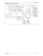
Страница 134: ...Wiring Diagrams 124 Outdoor Units MOU 24HDN1 Q 220075301400 MOU 24HDN1 Q 220075302030...
Страница 135: ...Wiring Diagrams Outdoor Units 125 MOU 30HDN1 Q MOU 36HDN1 Q 220075501600...
Страница 136: ...Wiring Diagrams 126 Outdoor Units MOU 36HDN1 Q 220075501990...
Страница 137: ...Wiring Diagrams Outdoor Units 127 MOU 48HDN1 Q MOU 48HDN1 Q New Body...
Страница 138: ...Wiring Diagrams 128 Outdoor Units MOU 36HDN1 R MOU 48HDN1 R MOU 60HDN1 R...
Страница 139: ...Wiring Diagrams Outdoor Units 129 MOU 48HDN1 R MOU 60HDN1 R New Body...
Страница 223: ...Troubleshooting Electrical Control System 213 2 4 2 9 E6 malfunction Only for 36K 48K with 1 phase...
Страница 224: ...Troubleshooting 214 Electrical Control System 2 4 2 10 P0 malfunction...
Страница 225: ...Troubleshooting Electrical Control System 215 2 4 2 11 P1 malfunction Only for 30K 60K...
Страница 226: ...Troubleshooting 216 Electrical Control System 2 4 2 12 P2 malfunction Only for 30K 60K...
Страница 227: ...Troubleshooting Electrical Control System 217 2 4 2 13 P3 malfunction...

