Midea 22031020003641 Скачать руководство пользователя страница 10


                                                                              Service Manual_2018-V2.0


10


4. Installation and commissioning 

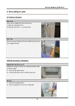
4.1Door Disassembly and Assembly (None) 

The refrigerator door needs to be dismantled if it cannot enter the room in the whole. 

Disassembly of Freezer door 

Disassembly of Freezer door 

None 

Disassembly of refrigerator door


Disassembly of refrigerator door 

None 

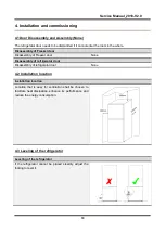
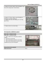
4.2 Installation location 

Installation location 

Location  that  is  easy  for  ventilation  shall  be  chosen  to 

facilitate  heat  dissipation,  enhance  its  performance  and 

reduce the energy consumption. 


4.3 Leveling of the refrigerator 

Leveling of the refrigerator 

If  the  refrigerator  cannot  be  placed  steadily,  adjust  the 

footing to level it. 


Содержание 22031020003641

Страница 1: ...BCD510WE UT 22031020004504 HD 663FWEN UR BCD510WE DQ 22031020003641 The picture in this service manual is only for reference and specific appearance and configuration are subject to the real product...

Страница 2: ...rmission of manufacturer WARNING Important Safety Notice The Maintenance Manual is only for the use of maintenance personnel with certain experience and background in electrical electronic and mechani...

Страница 3: ...NAL DIMENSION 14 5 3 LOCATION OF S N 15 6 PRODUCT SPECIFICATION 16 6 1 ELECTRICAL PARAMETERS 16 6 2 COOLING TEMPERATURE SETTING RANGE 16 6 3 DEFROSTING PARTS 17 6 4 CIRCUIT DIAGRAM 17 6 5MAIN CONTROL...

Страница 4: ...PEN DOOR ALARM NONE 35 10 5 FUNCTION SELECTION 35 10 6 FAULT CODE AND SOLUTIONS 35 10 7 DEFROSTING FUNCTION 35 10 8 TEST MODE 35 11 COMPRESSOR 37 11 1COMPRESSOR ON AND OFF CONTROL SPECIFICATIONS 37 12...

Страница 5: ...Service Manual_2018 V2 0 5 1 Significant update notes None...

Страница 6: ...ear any heat sources such as radiators heat registers stoves or other apparatus that produce heat 10 Do not defeat the safety purpose of the polarized or grounding type plug A polarized plug has two b...

Страница 7: ...e the shelves in place so that children may not easily climb inside 7 Unplug the freezer before carrying out user maintenance on it 8 This freezer can be used by children age eight years and older and...

Страница 8: ...tions are not completely understood or if doubt exists as to whether the freezer is properly grounded 2 2 Safety instruction for refrigerant Explosion Hazard Keep flammable materials and vapors such a...

Страница 9: ...otect the refrigerator in moving it Same as shown as lef t photo please move it by handcart with cushion 2 Remove all packing materials and bottom cushion the m ove into house for placement 3 After mo...

Страница 10: ...y of Freezer door None Disassembly of refrigerator door Disassembly of refrigerator door None 4 2 Installation location Installation location Location that is easy for ventilation shall be chosen to f...

Страница 11: ...reuse 5 Put on the cushion block lie down the refrigerator re move the 3 bolts fixed the lower hinge with the sleeve re move the lower hinge and adjust the foot 6 Remove the door block from the botto...

Страница 12: ...w holes on the right side of the top with the cover plate you previously removed 4 5 Installation of handle Installation of handle Installation of handle 1 Precautions shall be taken to prevent fall o...

Страница 13: ...duct Freezer chamber Refrigerator chamber glass shelf of freezer room Air duct assembly of freezer room small tray of freezer room Air duct assembly of refrigerator room Glass shelf of refrigerator ro...

Страница 14: ...663FWEN Size mm Height to Top of Case A 1677 1677 Width B 750 750 Depth w Cabinet C 705 705 Depth w Door D 784 5 784 5 Depth w Handle E Depth Door open 90 deg w F 1485 5 1485 5 Depth Door open 135 deg...

Страница 15: ...Service Manual_2018 V2 0 15 5 3 Location of S N Some products also have S N on the lower part of the right side of the Cabinet...

Страница 16: ...compressor wiring terminal Rmc 20 73 7 Rsc 17 98 7 Rms Rmc Rsc Rmc 5 35 7 Rsc 8 01 7 Rms Rmc Rsc Winding resistance picture The input power of compressor 93 6W 93 3W Motor Fan motor of the freezing c...

Страница 17: ...6 3 Defrosting parts Electronic type Item Specification Defrosting sensor Fuse 77 0 4 77 0 4 Defrost heater in freezing chamber 230V 250W 115V 180W 6 4 Circuit diagram F Freezer R Refrigerator FD Free...

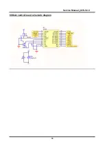
Страница 18: ...Service Manual_2018 V2 0 18 6 5Main control board schematic diagram...

Страница 19: ...efrigerating piping system and circulating route of cooling air 7 1 Refrigerating piping system Compressor Anti condensation tube Condenser Dry filter Capillary tube Evaporator Suction tube Compressor...

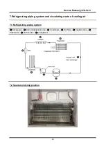
Страница 20: ...Service Manual_2018 V2 0 20 7 3 Circulating route of cooling air...

Страница 21: ...or tray While squeezing it inward lift up the baffle and take it out from refrigerator liner 8 2Parts inside the refrigerator Refrigerator Fruit box cover Remove the crisper cover of ref compartement...

Страница 22: ...f the refrigerating Light of the refrigerating chamber is located upper chamber inner display 1 Remove the lamp cover 2 Remove the bulb 3 The reverse process can complete installation Light of the fre...

Страница 23: ...ir duct components in freezing chamber and fan motor None Air duct components in freezing chamber All accessories in the freezing chamber should be dismantled before removing the air duct components 1...

Страница 24: ...ade pull it out using great force 5 Replace the fan in reverse steps 8 6 Evaporator and Defrost system Evaporator in freezing chamber Evaporator in freezing chamber 1 Remove the air duct components in...

Страница 25: ...f the band which fixes the sensor 3 Separate the sensor and the evaporator Don t break the welding of the evaporator in case that only the sensor needs to be replaced Defrost heater The defrost heater...

Страница 26: ...a solid enough object leaving space to facilitate the operation For safety it should be carried by someone to prevent its falling 3 Cut off the compressor pipeline Cut off the process pipeline Cut off...

Страница 27: ...ll it out and remove it 7 Remove the starter and protector Unplug the starter and protector you can use a screwdriver to pry it slowly 8 Loosen the screw of the compressor bottom plate remove the floo...

Страница 28: ...Replace the compressorand welding the compressor pipeline Welding the process pipeline Welding the low pressure muffler Welding the high pressure exhaust pipe 12 Replace the filter Cu Fe tubes welding...

Страница 29: ...nging wire tube condensor None Piping system in the compressor case Compressor Suction connection Pipe Drier Capillary Tube Anti condensation pipe Condenser Exhaust evaporation pipe 8 8 Display contro...

Страница 30: ...ion box with a straight screwdriver to get the master control board and installation box components 5 Pry open the buckle of the PCB installation box with a straight screwdriver to see the PCB board 6...

Страница 31: ...igerating chamber Sensor in Variable temperature chamber Ambient temperature or humidity sensor Ice machine sensor Defrost sensor in refrigerating chamber Defrost sensor freezing chamber Sensor in ref...

Страница 32: ...rost sensor is located on top of the evaporator 1 Disconnect the connector of defrost sensor 2 Cut off the band which fixes the sensor 3 Separate the sensor and the evaporator Sensor replacement guide...

Страница 33: ...20 2 501 35 1 312 24 23 76 9 10 35 6 4 818 21 2 391 36 1 259 23 22 43 8 9 82 7 4 589 22 2 287 37 1 209 22 21 18 7 9 316 8 4 372 23 2 188 38 1 161 21 20 01 6 8 841 9 4 167 24 2 094 39 1 115 20 18 9 5...

Страница 34: ...LED light group will display fault code circular display If no failure occurs the current operation gear will be displayed Note Inner display product the gear LED light is off when the refrigerator do...

Страница 35: ...oard is welll stuck pull out the terminal and re stick it in place Step 2 Check to see if there re foreign matters on the terminal Step 3 Inspect the defrost sensor whether contact is bad and resend c...

Страница 36: ...in then the refrigerator will exit the test mode and return to normal operation mode In forced defrosting mode if the temperature of defrosting sensor is always lower than 12 C and the defrosting heat...

Страница 37: ...conditions is met the compressor stops 1 Tr Trt 2 The compressor runs continuously for more than 3 hours Stop 5 minutes 1 2 When all the following conditions are met the compressor starts up 1 Tr Trk...

Страница 38: ...Service Manual_2018 V2 0 38 12 Troubleshooting Method 12 1 No cooling Air cooling Electronic...

Страница 39: ...Service Manual_2018 V2 0 39 12 2 No working of compressor 12 3 Inside frosting no defrosting...

Страница 40: ...Service Manual_2018 V2 0 40 12 4 Inside frosting no defrosting Maintenance guidelines...

Страница 41: ...Service Manual_2018 V2 0 41 12 5 Light is not on 12 6 Fan failure...

Страница 42: ...Service Manual_2018 V2 0 42 12 7 Defective defrost circuit 12 8 Noise...

Страница 43: ...Service Manual_2018 V2 0 43 12 9 Air duct not operated electronically None...

Страница 44: ...Service Manual_2018 V2 0 44 13 Figures and details of repair parts See this section in the TSP...

Страница 45: ...g please contact your local authority or where you purchased your product MIDEA appliances after sales website For more information about Midea appliances after sales please visit the tsp midea com Fo...

Отзывы: