IGLOO nano Starter Kit
R e v i s i o n 3
21
Flash*Freeze Switch
Flash*Freeze technology enables the user to quickly (within 1 µs) enter and exit Flash*Freeze mode by
activating the Flash*Freeze pin while all power supplies are kept at their original values. I/Os, global I/Os,
and clocks can still be driven and can be toggling without impact on power consumption, and the device
retains all core registers, SRAM information, and I/O states. I/Os can be individually configured to either
hold their previous states or can be tristated during Flash*Freeze mode.
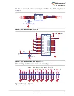
An F*F switch is provided on the board for designs that utilize the Flash*Freeze technology. Setting the
F*F switch to FF_ON will enable the Flash*Freeze mode of the IGLOO nano device. In the Flash*Freeze
schematic shown in
, the Schmitt device is use to reduce noise on the F*F input of the IGLOO
nano FPGA. This Schmitt device can be bypassed with a resistor because an AGLN250 FPGA supports
additional I/O advanced features such as Schmitt trigger.
Figure 3-3 • Flash*Freeze Mode Control
Figure 3-4 • Flash*Freeze Schematic
Actel IGLOO nano
FPGA
Flash*Freeze
Mode Control
Flash*Freeze Pin
VCC_3_3
VCC_3_3
agl_ff
[4,8]
C45
100n-0603
C45
100n-0603
2
1
3
SW6
AYZ0102AGRL
SW6
AYZ0102AGRL
C44
2u2-TantA
C44
2u2-TantA
R29
NL-0R-0603
R29
NL-0R-0603
C43
10u-TantA
C43
10u-TantA
C42
100n-0603
C42
100n-0603
R28
10K-0603
R28
10K-0603
NC
1
2
A
GND
3
VCC
5
4
Y
U7
SN74AUP1G17DCKR-SC70-5
U7
SN74AUP1G17DCKR-SC70-5
Содержание IGLOO nano Starter Kit
Страница 1: ...IGLOO nano Starter Kit User s Guide ...
Страница 6: ......
Страница 9: ...IGLOO nano Starter Kit Revision 3 9 Figure 1 3 Bottom Silkscreen ...
Страница 14: ......
Страница 28: ......
Страница 30: ......
Страница 32: ......
Страница 34: ......
Страница 36: ......
Страница 41: ......

