Signal
Specifications
Each
serial
signal
(control,
status,
data,
or
clock)
is
compatible
with
an
electrical
specification
that
is
selected
by
placement
of
jumpers
on
the
card.
This
section
briefly
describes
the
specifications
supported
by
the
card.
Single
Ended
Signals
(RS
232/V.28)
Single
ended
signals
supported
by
the
card
are
compatible
with
both
RS
‐
232
and
ITU
V.28
standards.
Each
single
ended
signal
uses
one
conductor
in
a
cable,
and
all
single
ended
signals
share
a
common
ground
conductor.
•
Maximum
Voltage
Range:
+15
to
‐
15V
(between
signal
and
ground)
•
+3V
to
+15V
(+5V
typical)
=
control/status
signal
on
or
data
value
of
0
•
‐
3V
to
‐
15V
(
‐
5V
typical)
=
control/status
signal
off
or
data
value
of
1
•
Voltage
between
‐
3V
to
+3V
=
invalid
(indeterminate)
state
•
Max
cable
length
50
feet
•
Max
data
rate
20kbps
The
maximum
data
rate
of
20kbps
is
part
of
the
RS
‐
232/V.28
standards.
The
SyncLink
card
can
operate
at
speeds
up
to
120kbps
depending
on
the
cable
length
and
loading.
Longer
cables
and
increased
loading
reduces
the
maximum
supported
data
rate.
Differential
Signals
(RS
422/RS
485/V.11)
Differential
signals
supported
by
the
card
are
compatible
with
RS
‐
422,
RS
‐
485
and
ITU
V.11
standards.
Each
differential
signal
uses
two
conductors
in
a
cable
(signal
pair).
A
common
ground
conductor
is
recommended
for
use
with
differential
signals
to
reduce
common
mode
voltages
between
cable
ends
which
may
result
in
incorrect
or
impaired
operation.
•
Maximum
Voltage
Range:
+5
to
‐
5V
(between
conductors
in
a
pair)
•
+200mV
to
+5V
(+2V
typical)
=
control/status
signal
on
or
data
value
of
0
•
‐
200mV
to
‐
5V
(
‐
2V
typical)
=
control/status
signal
off
or
data
value
of
1
•
Voltage
between
‐
200mV
to
+200mV
invalid
(indeterminate)
state
•
Max
cable
length
4000
feet
•
Max
data
rate
10Mbps
Longer
cables
and
increased
loading
reduces
the
maximum
supported
data
rate.
Clock
Polarity
Synchronous
serial
communications
(HDLC/Bisync/Monosync)
may
use
separate
clock
signals
to
control
the
timing
of
data
signals.
One
clock
cycle
equals
one
bit.
There
are
two
clock
edges
(rising
and
falling)
for
each
clock
cycle.
On
one
edge,
the
transmit
data
output
changes.
On
the
other
edge,
the
receive
data
input
is
sampled.
The
assignment
of
clock
edges
to
transmit
data
transition
and
receive
data
sampling
is
referred
to
as
clock
polarity.
Содержание SyncLink GT2
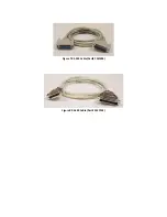
Страница 14: ...Figure 7 RS 530 Cable Part CMF000 Figure 8 RS 449 Cable Part 2537FM ...
Страница 18: ......


