background image

Finding the COM Port Number

You will need to know the COM port number the RS-485 MicroLink-HM modem is connected to.  To see a list of COM 
ports installed on your PC, open the Device Manager and select 

View > Devices by Type

.  Expand 

Ports (COM & LPT)

 to 

see the list of available COM ports. RS-485 MicroLink-HM is compa  ble with RS-485 to USB or RS-232 serial converters.  

HART Protocol Modem

The RS-485 MicroLink-HM ships con

fi

 gured to operate as a HART protocol modem.  Connect the A and B terminals to 

an RS-485 port and  provide a power supply.  Power must be supplied by an external 5 to 30 volts DC power supply. 
Refer to the 

Power Supply

 sec  on in this manual for details. If your PC does not have an RS-485 port you will need to 

use an RS-485 converter.  Micro

fl

 ex o

 ers the 101-0020 USB to RS-485 converter and the 101-0009  RS-232 to RS-485 

converter. 

RS-485 MicroLink-HM is compa  ble with most HART con

fi

 gura  on and test so  ware. Included on the CD is the 

PACTware FDT frame, HART Protocol DTM, and Micro

fl

 ex Generic DTM so  ware. For informa  on on installing PACTware 

and the DTM, please reference the PACTware Quick Start Guide. 

To func  on as a HART protocol modem the serial port is typically set to 1200 baud, odd parity.  Most HART so  ware 
will require this se   ng.  It is possible to set the serial port to other baud rates and parity se   ngs. This is helpful when 
connec  ng the RS-485 MicroLink-HM to a device that does not o

 er 1200 baud. In this case RS-485 MicroLink-HM will 

receive the HART command at the higher baud rate then transmit the HART data at 1200 baud, odd parity onto the 
HART loop. The 1200 baud, odd parity HART reply packet is received by the RS-485 MicroLink-HM modem and then 
transmi  ed back at the higher baud rate.

If the RS-485 MicroLink-HM is con

fi

 gured to Fill Modbus Registers and it detects a HART packet on the network, RS-485 

MicroLink-HM will temporarily switch to HART mode and stop polling devices.  HART protocol packets always begin 
with the hex FF preamble character. Modbus packets begin with the slave address. If no HART commands are received 
over the serial port, RS-485 MicroLink-HM will return to polling and 

fi

 lling modbus registers a  er 30 seconds.  Also, if a 

modbus command is received MicroLink will exit HART mode and return to polling and 

fi

 lling modbus registers. 

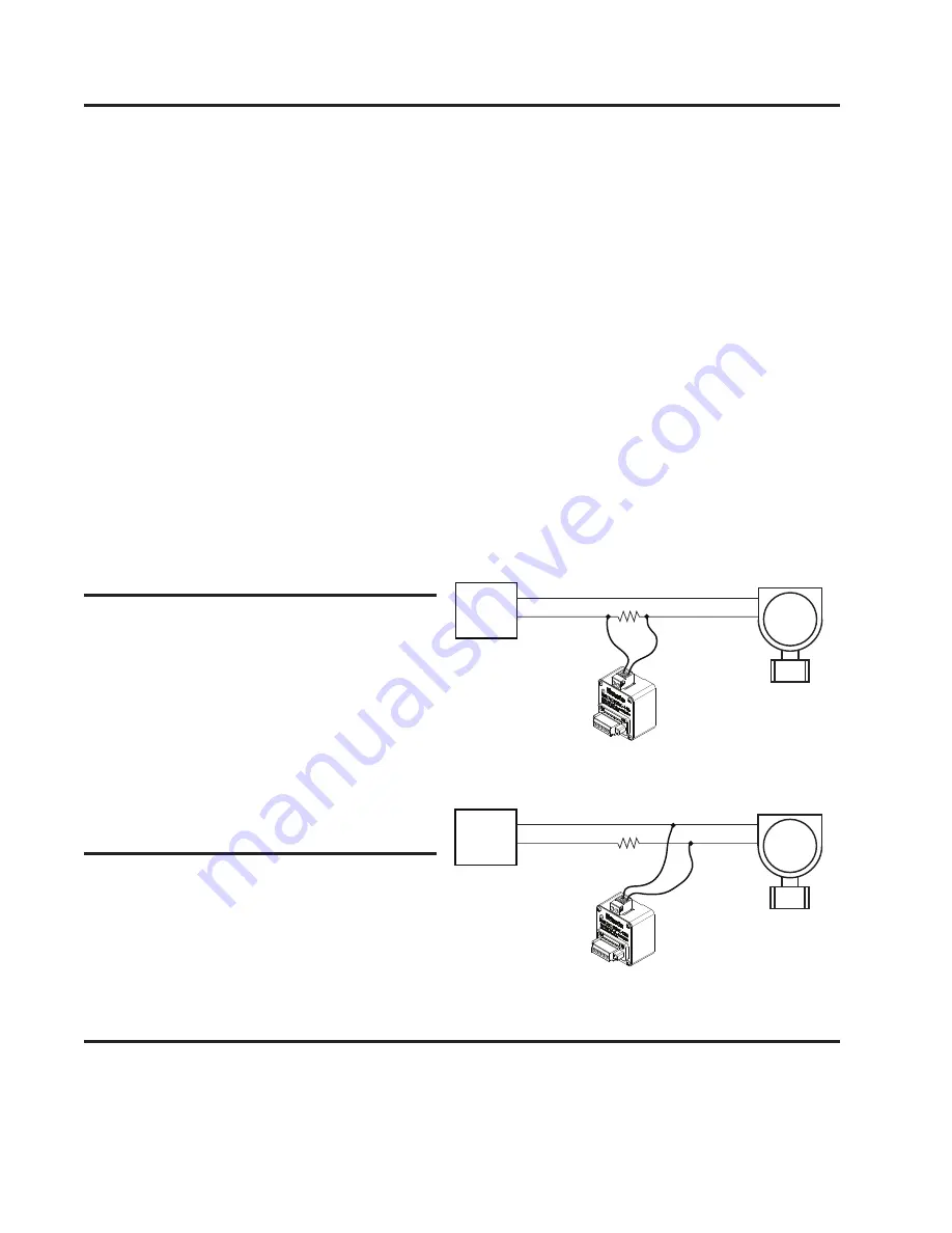
Connecting to the HART Loop

Connect the two screw terminals to the HART device 
or HART loop.  Microlink provides electrical isola  on 
between the HART loop and the serial port so it is safe 
to ignore grounding and polarity issues when making 
the HART connec  ons.  The HART protocol requires a 
loop resistance of 230 to 600 ohms, typically 250 ohms. 
Refer to your equipment installa  on instruc  ons for 
details on connec  ng a HART master or con

fi

 gura  on 

device to the loop.

HART Status LED Operation

The LED on the front panel of the RS-485 MicroLink-HM 
is used to monitor HART communica  ons ac  vity. The 
LED will be green while transmi   ng or sending a packet 
to your HART protocol devices, and will be red when 
HART protocol replies are received.  

LOOP

POWER
SUPPLY

HART

DEVICE

250Ω

LOOP

POWER
SUPPLY

HART

DEVICE

250Ω

Figure 1. Connec  ng HART modem to device loop.

Connecting across the loop resistor.

Connecting across the HART device.

Содержание MicroLink-HM 101-0035

Страница 1: ...sducer devices HART and an RS 485 network Serial port baud rates can be set from 1200 to 57 600 and parity can be odd even or none HART protocol communica ons between the RS 485 MicroLink HM and HART devices is always 1200 baud odd parity RS 485 MicroLink HM can be configured to poll up to 16 HART devices and save the HART device data into modbus registers Modbus RTU commands can then be used to r...

Страница 2: ...d rate then transmit the HART data at 1200 baud odd parity onto the HART loop The 1200 baud odd parity HART reply packet is received by the RS 485 MicroLink HM modem and then transmi ed back at the higher baud rate If the RS 485 MicroLink HM is configured to Fill Modbus Registers and it detects a HART packet on the network RS 485 MicroLink HM will temporarily switch to HART mode and stop polling d...

Страница 3: ...indows PC or laptop and make the necessary se ngs Connect the A and B terminals to an RS 485 port If your PC does not have an RS 485 port you will need to use an RS 485 converter Microflex offers the 101 0020 USB to RS 485 converter and the 101 0009 RS 232 to RS 485 converter Power must be supplied by an external 5 to 30 volts DC power supply Refer to the Power Supply sec on in this manual for deta...

Страница 4: ... single device or up to 16 devices When more than one device is in the loop each HART device must have a unique HART polling address The address for each device is set before wiring the device into the multi drop loop The device polling address for each device is stored in the RS 485 MicroLink HM using the RS 485 MicroLink HM configuration software Modbus slave address baud rate parity and other s...

Страница 5: ... Protocol Se ngs window will expand to show the Polled Devices se ngs Retries If a HART devices is polled but does not respond or errors are detected RS 485 MicroLink HM can retry up to 3 mes before indica ng a bad device If a device is not responding the Modbus values are filled with Hart Device Failed register values setup is done in the Modbus configura on sec on Polled Devices In the example s...

Страница 6: ...es When device data is stored into a 16 bit signed Modbus register the value can range from 32768 to 32767 To allow the 16 bit integer to represent a smaller number and include frac onal informa on the number of decimal places is stored in a separate Modbus register and applied later The number of decimal places can be set from 0 to 5 Decimal places can be set for each variable The Device Variable...

Страница 7: ...r integers Bits 7 6 HART poll retries Sets number of HART device poll retries from 1 to 3 After poll retries the HART failed mode value is stored in the variable register Bit 5 0 Fill Modbus registers 1 HART modem mode Bits 3 0 Number of polled devices 1 Range is 0 to 15 0 1 polled device 15 16 polled devices ϭϱ ϭϰ ϭϯ ϭϮ ϭϭ ϭϬ ϵ ϴ ϳ ϲ ϱ ϰ ϯ Ϯ ϭ Ϭ Zd ĂŝůĞĚ DŽĚĞ ŝƚ ϭͿ Zd ĂŝůĞĚ DŽĚĞ ŝƚ ϬͿ Zd ZĞƚƌŝĞƐ ...

Страница 8: ... 01 Even 10 Odd Mode Settings Bit 9 Floating point value byte order 0 Standard byte order AB CD 1 Swapped words CD AB Bit 8 Modbus device map 0 Map register data by HART device 1 Map register data by variable type ϭϱ ϭϰ ϭϯ ϭϮ ϭϭ ϭϬ ϵ ϴ ϳ ϲ ϱ ϰ ϯ Ϯ ϭ Ϭ Ϭс ĨůŽĂƚ ďLJƚĞ ŽƌĚĞƌ ϭс ϬсďLJ ĞǀŝĐĞ DĂƉ ϭсďLJ sĂƌŝĂďůĞ DĂƉ ϳϳϰ Ͳ DŽĚĞ ĞƚƚŝŶŐƐ Bits 11 8 1 1200 Baud 2 2400 3 4800 4 9600 5 14400 6 19200 7 38400 8 5760...

Страница 9: ...Ğ dLJƉĞ ϭ ϳϯϮ Ϯ ϯ ϭϮ ϳϯϯ WƌĞĂŵďůĞƐ DĂŶ ŽĚĞ Žƌ dLJƉĞ ϳϯϰ ĞǀŝĐĞ dLJƉĞ ϭ ϳϯϱ Ϯ ϯ ϭϯ ϳϯϲ WƌĞĂŵďůĞƐ DĂŶ ŽĚĞ Žƌ dLJƉĞ ϳϯϳ ĞǀŝĐĞ dLJƉĞ ϭ ϳϯϴ Ϯ ϯ ϭϰ ϳϯϵ WƌĞĂŵďůĞƐ DĂŶ ŽĚĞ Žƌ dLJƉĞ ϳϰϬ ĞǀŝĐĞ dLJƉĞ ϭ ϳϰϭ Ϯ ϯ ϭϱ ϳϰϮ WƌĞĂŵďůĞƐ DĂŶ ŽĚĞ Žƌ dLJƉĞ ϳϰϯ ĞǀŝĐĞ dLJƉĞ ϭ ϳϰϰ Ϯ ϯ ϭϲ ϳϰϱ WƌĞĂŵďůĞƐ DĂŶ ŽĚĞ Žƌ dLJƉĞ ϳϰϲ ĞǀŝĐĞ dLJƉĞ ϭ ϳϰϳ Ϯ ϯ Polled HART Devices Long Address Table Device ID informa on is read from each polled device u...

Страница 10: ...ƚĞͿ ϭ ϳϱϲ WsͲ dsͲ s Ϯ ϳϱϳ WsͲ dsͲ s ϯ ϳϱϴ WsͲ dsͲ s ϰ ϳϱϵ WsͲ dsͲ s ϱ ϳϲϬ WsͲ dsͲ s ϲ ϳϲϭ WsͲ dsͲ s ϳ ϳϲϮ WsͲ dsͲ s ϴ ϳϲϯ WsͲ dsͲ s ϵ ϳϲϰ WsͲ dsͲ s ϭϬ ϳϲϱ WsͲ dsͲ s ϭϭ ϳϲϲ WsͲ dsͲ s ϭϮ ϳϲϳ WsͲ dsͲ s ϭϯ ϳϲϴ WsͲ dsͲ s ϭϰ ϳϲϵ WsͲ dsͲ s ϭϱ ϳϳϬ WsͲ dsͲ s ϭϲ ϳϳϭ WsͲ dsͲ s Number of Decimal Places Table When storing the HART variable data in 16 bit modbus registers the maximum range is 32768 to 32767 To ...

Страница 11: ...ƚĞŐĞƌ ϭϬ ds ŶƚĞŐĞƌ ϯϰ ds ŶƚĞŐĞƌ ϭϭ s ŶƚĞŐĞƌ ϯϱ s ŶƚĞŐĞƌ ϭϮ Zd ƚĂƚƵƐ ϯϲ Zd ƚĂƚƵƐ ϭϯ D с Ws hKD с s hKD ϯϳ D с Ws hKD с s hKD ϭϰ D с ds hKD с s hKD ϯϴ D с ds hKD с s hKD Ϯϲϰ Ϯϲϱ Ws ůŽĂƚ Ϯϴϴ Ϯϴϵ Ws ůŽĂƚ Ϯϲϲ Ϯϲϳ s ůŽĂƚ ϮϵϬ Ϯϵϭ s ůŽĂƚ Ϯϲϴ Ϯϲϵ ds ůŽĂƚ ϮϵϮ Ϯϵϯ ds ůŽĂƚ ϮϳϬ Ϯϳϭ s ůŽĂƚ Ϯϵϰ Ϯϵϱ s ůŽĂƚ ĞǀŝĐĞ ϯ ĞǀŝĐĞ ϲ ϭϲ Ws ŶƚĞŐĞƌ ϰϬ Ws ŶƚĞŐĞƌ ϭϳ s ŶƚĞŐĞƌ ϰϭ s ŶƚĞŐĞƌ ϭϴ ds ŶƚĞŐĞƌ ϰϮ ds ŶƚĞŐĞƌ ϭϵ s ŶƚĞŐĞƌ ϰϯ s...

Страница 12: ...ϴϬ Ws ŶƚĞŐĞƌ ϱϳ s ŶƚĞŐĞƌ ϴϭ s ŶƚĞŐĞƌ ϱϴ ds ŶƚĞŐĞƌ ϴϮ ds ŶƚĞŐĞƌ ϱϵ s ŶƚĞŐĞƌ ϴϯ s ŶƚĞŐĞƌ ϲϬ Zd ƚĂƚƵƐ ϴϰ Zd ƚĂƚƵƐ ϲϭ D с Ws hKD с s hKD ϴϱ D с Ws hKD с s hKD ϲϮ D с ds hKD с s hKD ϴϲ D с ds hKD с s hKD ϯϭϮ ϯϭϯ Ws ůŽĂƚ ϯϯϲ ϯϯϳ Ws ůŽĂƚ ϯϭϰ ϯϭϱ s ůŽĂƚ ϯϯϴ ϯϯϵ s ůŽĂƚ ϯϭϲ ϯϭϳ ds ůŽĂƚ ϯϰϬ ϯϰϭ ds ůŽĂƚ ϯϭϴ ϯϭϵ s ůŽĂƚ ϯϰϮ ϯϰϯ s ůŽĂƚ ĞǀŝĐĞ ϵ ĞǀŝĐĞ ϭϮ ϲϰ Ws ŶƚĞŐĞƌ ϴϴ Ws ŶƚĞŐĞƌ ϲϱ s ŶƚĞŐĞƌ ϴϵ s ŶƚĞŐĞƌ ϲϲ ds ŶƚĞŐ...

Страница 13: ... D с ds hKD с s hKD ϯϱϮ ϯϱϯ Ws ůŽĂƚ ϯϲϴ ϯϲϵ Ws ůŽĂƚ ϯϱϰ ϯϱϱ s ůŽĂƚ ϯϳϬ ϯϳϭ s ůŽĂƚ ϯϱϲ ϯϱϳ ds ůŽĂƚ ϯϳϮ ϯϳϯ ds ůŽĂƚ ϯϱϴ ϯϱϵ s ůŽĂƚ ϯϳϰ ϯϳϱ s ůŽĂƚ ĞǀŝĐĞ ϭϰ ĞǀŝĐĞ ϭϲ ϭϬϰ Ws ŶƚĞŐĞƌ ϭϮϬ Ws ŶƚĞŐĞƌ ϭϬϱ s ŶƚĞŐĞƌ ϭϮϭ s ŶƚĞŐĞƌ ϭϬϲ ds ŶƚĞŐĞƌ ϭϮϮ ds ŶƚĞŐĞƌ ϭϬϳ s ŶƚĞŐĞƌ ϭϮϯ s ŶƚĞŐĞƌ ϭϬϴ Zd ƚĂƚƵƐ ϭϮϰ Zd ƚĂƚƵƐ ϭϬϵ D с Ws hKD с s hKD ϭϮϱ D с Ws hKD с s hKD ϭϭϬ D с ds hKD с s hKD ϭϮϲ D с ds hKD с s hKD ϯϲϬ ϯϲϭ Ws ů...

Страница 14: ...ϲϯ ϳϵ ϵϱ ϭϭϭ Zd Ws s ds Ys ĞǀŝĐĞ ůŽĂƚ ůŽĂƚ ůŽĂƚ ůŽĂƚ ϭ Ϯϱϲ Ϯϱϳ Ϯϴϴ Ϯϴϵ ϯϮϬ ϯϮϭ ϯϱϮ ϯϱϯ Ϯ Ϯϱϴ Ϯϱϵ ϮϵϬ Ϯϵϭ ϯϮϮ ϯϮϯ ϯϱϰ ϯϱϱ ϯ ϮϲϬ Ϯϲϭ ϮϵϮ Ϯϵϯ ϯϮϰ ϯϮϱ ϯϱϲ ϯϱϳ ϰ ϮϲϮ Ϯϲϯ Ϯϵϰ Ϯϵϱ ϯϮϲ ϯϮϳ ϯϱϴ ϯϱϵ ϱ Ϯϲϰ Ϯϲϱ Ϯϵϲ Ϯϵϳ ϯϮϴ ϯϮϵ ϯϲϬ ϯϲϭ ϲ Ϯϲϲ Ϯϲϳ Ϯϵϴ Ϯϵϵ ϯϯϬ ϯϯϭ ϯϲϮ ϯϲϯ ϳ Ϯϲϴ Ϯϲϵ ϯϬϬ ϯϬϭ ϯϯϮ ϯϯϯ ϯϲϰ ϯϲϱ ϴ ϮϳϬ Ϯϳϭ ϯϬϮ ϯϬϯ ϯϯϰ ϯϯϱ ϯϲϲ ϯϲϳ ϵ ϮϳϮ Ϯϳϯ ϯϬϰ ϯϬϱ ϯϯϲ ϯϯϳ ϯϲϴ ϯϲϵ ϭϬ Ϯϳϰ Ϯϳϱ ϯϬϲ ϯϬϳ ϯϯϴ ϯϯϵ ϯϳϬ ϯϳϭ ϭϭ Ϯϳϲ...

Страница 15: ... inser on or removal Common mode range permits 7V ground difference Specifications PP PP PP 57 223 5 6 5 7 50 1 PP PP 1 5 3 67 786 56 3257 32 5 6 5 7 50 1 Modbus RTU Floa ng point byte order AD CD or CD AB swapped Number of polled HART devices 1 to 16 Variables per polled HART device 4 PV SV TV FV Supported Modbus Commands 3 6 16 HART Termina on Pluggable Screw Terminals 26 12 AWG Connec on Method ...

Страница 16: ...95 A1 1998 A2 2001 Radiated Immunity EN 61000 4 3 2002 Safety Compliance EN 60950 1 2002 This device does not have protection from over voltages which may exist on RS 232 ports of computers and relies on the protection existing in a host computer This device is not intended for connection to the phone line through the appropriate converters and shall not be connected to telecommunication lines bec...

Страница 17: ...POSE CUSTOMER S RIGHT TO RECOVER DAMAGES CAUSED BY FAULT OR NEGLIGENCE ON THE PART OF MICROFLEX SHALL BE LIMITED TO THE AMOUNT THERETOFORE PAID BY THE CUSTOMER MICROFLEX LLC WILL NOT BE LIABLE FOR DAMAGES RESULTING FROM LOSS OF DATA PROFITS USE OF PRODUCTS OR INCIDENTAL OR CONSEQUENTIAL DAMAGES EVEN IF ADVISED OF THE POSSIBILITIES THEREOF This limitation of the liability of Microflex LLC will appl...

Отзывы: