MC20-X/10-4
Doc. N°
MO-0352-ING
Microener - Copyright 2010
FW
720.07.01
Date
09.04.2008
Rev.
1
Pag.
30
of
35
Страница 1: ...MC20 X 10 4 Doc N MO 0352 ING Microener Copyright 2010 FW 720 07 01 Date 09 04 2008 Rev 1 MICROPROCESSOR OVERCURRENT and EARTH FAULT RELAY TYPE MC20 X 10 4 I O Boards OPERATION MANUAL...
Страница 2: ..._______________________ 15 2 2 5 13 LCD Display and Buzzer operation ____________________________________________________________________ 15 3 Logic Blocking of Functions______________________________...
Страница 3: ...Loading must be compatible with their declared performance 1 6 Protection Earthing When earthing is required carefully check its effectiveness 1 7 Setting and Calibration Carefully check the proper s...
Страница 4: ...truction manual of the Manufacturer maintenance must be carried out by specially trained people and in strict conformity with the safety regulations 1 11 Waste Disposal of Electrical Electronic Equipm...
Страница 5: ...l Inputs RS485 communication port independent from the RS232 port on front panel Totally draw out execution with automatic C T shorting device Input currents are supplied to 3 current transformers two...
Страница 6: ...ents are measured whereas the current of the phase B is computed as vector summation of the currents of the other two phases The algorithm is based on the following considerations coming from well kno...
Страница 7: ...nt from I1 2 2 2 4 Algorithm of the time current curves The Time Current Curves are generally calculated with the following equation 1 where t I Actual trip time delay when the input current equals I...
Страница 8: ...MC20 X 10 4 Doc N MO 0352 ING Microener Copyright 2010 FW 720 07 01 Date 09 04 2008 Rev 1 Pag 8 of 35 2 2 3 Time Current Curves IEC TU1029 Rev 0...
Страница 9: ...MC20 X 10 4 Doc N MO 0352 ING Microener Copyright 2010 FW 720 07 01 Date 09 04 2008 Rev 1 Pag 9 of 35 2 2 4 Time Current Curves IEEE TU1028 Rev 0...
Страница 10: ...e Curve SI IEEE Short Inverse Curve BI Operation controlled by Blocking Digital Input Trg Function operation triggers the oscillographic wave form capture see 2 2 3 12 I Minimum phase current pick up...
Страница 11: ...vel limited to 40 times In t2xI Trip time delay tIH Trip time delay 2 2 5 3 1 Automatic doubling or Overcurrent thresholds on current inrush For some of the phase Overcurrent functions it is possible...
Страница 12: ...ve I IEEE Inverse Curve EI IEEE Extremely Inverse Curve SI IEEE Short Inverse Curve BI Operation controlled by Blocking Digital Input Trg Function operation triggers the oscillographic wave form captu...
Страница 13: ...Trip time delay 2 2 5 8 BF F51BF Breaker Failure FuncEnab Enable Disable Enable Options TrR Relay1 Relay1 Relay2 Relay3 Relay4 TripLev No Param No Parameters Timers tBF 0 20 s 0 05 0 75 step 0 01 s Fu...
Страница 14: ...is disactivated Trg Disab Function Disable no recording Start Trigger on time start of protection functions Trip Trigger on trip time delay end of protection functions Ext Inp Trigger from the Digita...
Страница 15: ...te Front panel RS232 communication speed Com RBd Remote Baud Rate Rear panel terminal blocks RS485 communication speed Com Mod Remote mode communication parameters Note Any change of this setting beco...
Страница 16: ...controlled by the activation of the Digital Input D1 BI Enable in this case the set trip time delay of the function is increased by 2xtBF so that other Protection Relays set with the same trip time d...
Страница 17: ...sion Module D1 Digital Input 1 D1 By the interface program MSCom 2 it is possible view the status or via RS485 port Modbus protocol D2 Digital Input 1 D2 D3 Digital Input 1 D3 D4 Digital Input 1 D4 D5...
Страница 18: ...lay can be totally managed locally either by the RS232 communication port or by the 4 key buttons and the LCD display or remotely via the communication bus RS485 connected to the rear terminal blocks...
Страница 19: ...ped reset takes places by pressing the reset button d Yellow LED PWR I R F Illuminated during normal operation when Power Supply is ON Flashing when a Relay Internal Fault is detected When any protect...
Страница 20: ...d the Communication Protocol is MODBUS RTU IEC60870 5 103 The configuration of transmission parameters is selectable Baud Rate 9600 19200 bps 9600 19200 bps 9600 19200 bps Start bit 1 1 1 Data bit 8 8...
Страница 21: ...ommunication Port on Front Face Panel This port is used for communication through the Front Face Panel between a local Lap top PC The physical link is RS232 by the standard female 9 pin D sub connecto...
Страница 22: ...er measurements to go back to Meas Display Description I 0 65535 In Largest of the 3 phase currents of rated current IA 0 65535 A RMS value of Phase A current Primary Amps IB 0 65535 A RMS value of Ph...
Страница 23: ...hich caused the relay tripping For indication of the TRIP Cause the following acronyms are used I 1 st Overcurrent Short Circuit I 2 nd Overcurrent Short Circuit IH 3 rd Overcurrent Short Circuit Io 1...
Страница 24: ...YY to set year XX MM to set month XX XX DD to set day XX XX XX hh mm to set hour XX mm to set minutes To validate Set Done Exit 11 5 3 RatedVal Rated Input Values RatedVal 1st Variable to scroll varia...
Страница 25: ...shold doubling 0 02 9 99 0 01 IH 3F51 FuncEnab Enable Enable of the protection function Enable Disable Options BI Disable Operation controlled by Blocking Digital Input Enable Disable 2xI Enable Autom...
Страница 26: ...le of the protection function Enable Disable Options Trg Trip Trigger operation mode Disable Start Trip Ext Inp TripLev No Parameters Timers tPre 0 30 Recording time before Trigger 0 10 0 50 0 1 tPost...
Страница 27: ...e N D N D Normally Deenergized N E Normally Energized N D N E R3 Link Ta I I IH Io Io IoH Association of functions to output relay R3 T Ta I tI I tI IH tIH Io tIo Io tIo tIoH BF RTD IRF HwRec CBopen C...
Страница 28: ...scription Clear Erase memory of Trip Counters Event Records Test Starts a relay diagnostic test Reset Reset after trip CBopen Manual Open Close Breaker CBclose Manual Close Close Breaker 11 8 Info Ver...
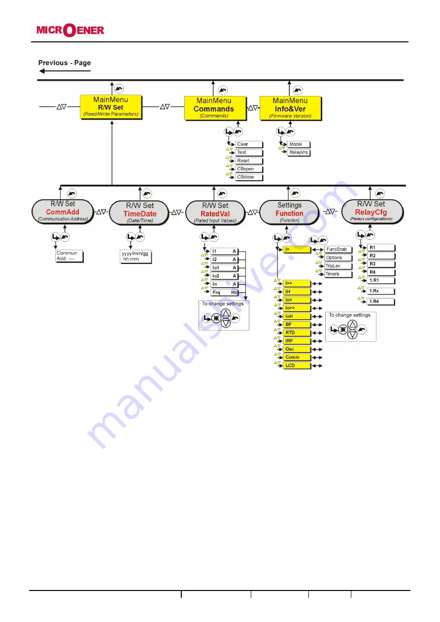
Страница 29: ...MC20 X 10 4 Doc N MO 0352 ING Microener Copyright 2010 FW 720 07 01 Date 09 04 2008 Rev 1 Pag 29 of 35 12 Keyboard Operational Diagram...
Страница 30: ...MC20 X 10 4 Doc N MO 0352 ING Microener Copyright 2010 FW 720 07 01 Date 09 04 2008 Rev 1 Pag 30 of 35...
Страница 31: ...s modification or to issue a command through the relay itself using the managing software MSCom The user can decide whether inserting his own password see MS Com Operational Manual or keeping the pass...
Страница 32: ...C20 X 10 4 Doc N MO 0352 ING Microener Copyright 2010 FW 720 07 01 Date 09 04 2008 Rev 1 Pag 32 of 35 16 Connection Diagram 16 1 UX10 4 Expansion Module Wiring Diagram 10 Digital Inputs 4 Output Relay...
Страница 33: ...MC20 X 10 4 Doc N MO 0352 ING Microener Copyright 2010 FW 720 07 01 Date 09 04 2008 Rev 1 Pag 33 of 35 17 Overall Dimensions...
Страница 34: ...orizontal position of the screws driver mark Draw out the PCB by pulling on the handle 18 2 Plug In Rotate clockwise the screws in the horizontal position of the screws driver mark Slide in the card o...
Страница 35: ...de disturbance 0Hz 150KHz IEC61000 4 16 level 4 Electrical fast transient burst IEC61000 4 4 level 3 2kV 5kHz HF disturbance test with damped oscillatory wave 1MHz burst test IEC60255 22 1 class 3 400...