DTMR3-TX
Doc. N°
MO-0377-ING
Copyright 2010
Data
01.04.2009
Rev.
0
Pag.
21
of
87
14.
Settings
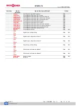
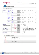
Two complete Group of setting of the programmable variables are available in the “
SETTING
” menu.
Both “Group 1” and “Group 2” include the below listed variables.
1
Indicates the Setting Group that is actually being modified.
This symbol indicates that the function is enabled; symbol missing
indicates that the function is disabled.
Comunic.
Serial communication parameters
LCD
Visualization parameters
1d>
First differential element
2d>
Second differential element
HLock
2
nd
and 5
th
Harmonic block
1I>
First overcurrent element
Side 1
1I>>
Second overcurrent element
Side 1
2I>
First overcurrent element
Side 2
2I>>
Second overcurrent element
Side 2
do1>
Earth Fault element
Side 1
do2>
Earth Fault element
Side 2
Wi
Amount of Energy to reach the C/B maintenance level
TCS
Setting variables for Trip Circuit Supervision
IRF
Internal Relay Fault
CB Mngm
C/B command Local / Remote setting
Oscillo
Setting variables for Oscillographic recording
BreakerFail
Setting variables for Breaker Failure detection
ExtReset
Configuration for external reset input


