background image

PRECISE-LOG Data Loggers User’s Manual  

Page 36/57


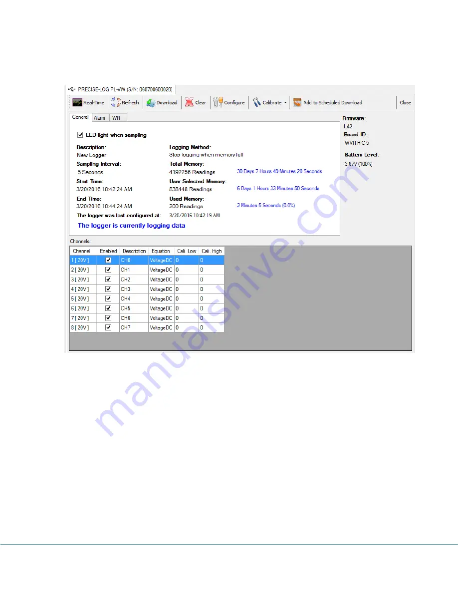
The status page shows the start and end time, sampling interval and other properties of the 
connected logger: 


General 

This sub tab page displays the general properties of the logger. 
 

Alarm 

This sub tab page displays the properties regarding the alarm. By clicking the “Alarm” tab 
page caption, the following page will appear: 
 

Содержание PRECISE -LOG

Страница 1: ...V4B 0A7 Toll Free 1 877 352 9158 www microedgeinstruments com Multi Channel Data Loggers PRECISE LOG 407 15216 North Bluff Road White Rock BC Canada V4B 0A7 Phone 604 424 9092 Toll Free 1 877 352 9158...

Страница 2: ...on with the furnishing performance or use of this material Copyright and Trademarks This manual contains proprietary information which is protected by copyright All rights are reserved No part of this...

Страница 3: ...budgeted service expenses and provide additional 2 years of protection at a fraction of the price of a repair 4 Return Policy Defective Product Return A Buyer may return a defective product to MEI for...

Страница 4: ...DIMENSION 9 Logger Diagram 9 USB Port Pin out Face In 10 Antenna 10 3 CHANNELS AND SENSOR CONNECTIONS 12 PL V PL VW WIFI ENABLED VOLTAGE INPUTS 12 Channel and Sensor Specifications 12 PL C PL CW WIFI...

Страница 5: ...35 General 36 Alarm 36 CONFIGURE LOGGER 38 Description 39 Sampling Interval 39 On Board LED 40 When Memory Full 40 Time to Start Time to End 40 Total Time Span 40 Enabled 40 Channel Range 41 Descripti...

Страница 6: ...PRECISE LOG Data Loggers User s Manual Page 5 57 6 SPECIFICATIONS 56 COMMON SPECIFICATIONS 56 LOGGING CAPACITY 57...

Страница 7: ...ing management and property configuration It has USB interface for local communications and a WIFI module for remote access PL x W Series PRECISE LOG data logger features a wide sampling interval rang...

Страница 8: ...emperature should be within 40 to 70 C 40 to 158 F 1 4 Identity of the logger Each logger has its own unique serial number which can be found on the back of the enclosure The serial number is used to...

Страница 9: ...d DC voltages in the range up to 20 VDC Any voltages over this range may cause permanent damage to the device Maximum Input Current Range For logger model PL C PL CW WIFI enabled The logger is designe...

Страница 10: ...s Manual Page 9 57 2 2 H Ha ar rd dw wa ar re e M Me ec ch ha an ni ic ca al l D Di im me en ns si io on n Logger Diagram For Model PL V PL VW WIFI enabled PL C PL CW WIFI enabled PL T PL TW WIFI ena...

Страница 11: ...Dimension 88 X 64 2 X 24 MM 3 46 X 2 53 X 0 95 Inches USB Port Pin out Face In 1 5 4 3 2 Pin1 External Power Supply 5 VDC Pin2 Logger Communications Receiver Line RX Pin3 Logger Communications Transm...

Страница 12: ...PRECISE LOG Data Loggers User s Manual Page 11 57...

Страница 13: ...has eight external voltage DC channels used to measure single ended voltage DC signals maximum of 20 volt The following figure illustrates the correct input connections Voltage External Input Connecti...

Страница 14: ...50 mA The following figure illustrates the correct input connections Current External Input Connections Note All inputs must share the same common ground Channel and Sensor Specifications Connections...

Страница 15: ...ctions Note All inputs must share the same common ground Channel and Sensor Specifications Connections Plugeable terminal block for eight external channels Channels CH0 on board thermistor 40 70 C 40...

Страница 16: ...e equation For detailed temperature range and voltage temperature look up table of a specific thermocouple type please refer to NIST s website at http srdata nist gov its90 download download html PL H...

Страница 17: ...y Thermistor channel 0 2 C 0 C 70 C External channels 0 2 FSR 25 C Measure Resistance SiteView provides factory resistance equation for measuring the resistor s value In Configuration dialog Choose Re...

Страница 18: ...PRECISE LOG Data Loggers User s Manual Page 17 57 In the pop up dialog enter new temperature coefficient values and click OK button...

Страница 19: ...stor equation is included in SiteView package When you create your own equation you can refer to this equation and replace those temperature coefficients with the ones obtained from the thermistor man...

Страница 20: ...hardware The following table lists all available built in equations for all channel types Channel Type Equation Name Equation Description Internal Thermistor Temperature Temperature External Thermisto...

Страница 21: ...time span the logger will wait after it takes the first sample and before it takes the second sample Logging Mode This parameter specifies if the logger will stop or continue logging when the memory...

Страница 22: ...time the desired start time will never reaches Click OK button to save new settings to the logger 2 The logger is now in Start Delay mode When you need to activate the logger press and hold the Activa...

Страница 23: ...ick blinking to indicate it will reset the CPU Release the button when you see this Then plug the logger to USB port of PC Site View should show it under the USB comm Tab Status LED PRECISE LOG logger...

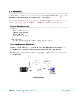
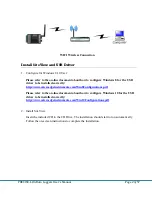
Страница 24: ...efer to SiteView User s Manual available for download online System Requirements Computer CPU 1 0 GHZ or above Memory 1 GB or above Port 1 USB port Hard Drive 1GB or above Operating System Window XP w...

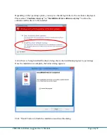
Страница 25: ...to be installed correctly http www microedgeinstruments com Win8Configurations pdf Please refer to the on line document about how to configure Windows 10 for the USB driver to be installed correctly...

Страница 26: ...PRECISE LOG Data Loggers User s Manual Page 25 57 Click Next button to proceed to the next page...

Страница 27: ...e read the License Agreement carefully If you accept the terms click I Agree then click Next button Otherwise click Cancel to cancel the installation If you have already followed the Windows 8 10 inst...

Страница 28: ...Page 27 57 In this dialog select a destination folder where SiteView will be installed We recommend you keep the default folder Once you are ready click Next button to proceed to the next page Click I...

Страница 29: ...Please select Continue Anyway or Install this driver software anyway to allow the software and the driver to be installed As SiteView is being installed the above dialog shows the installation progres...

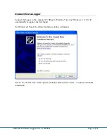
Страница 30: ...the logger to the computer s USB port Windows Vista and Windows 7 8 10 will automatically recognize the data logger For Windows XP user the following dialog window will appear Select No not this time...

Страница 31: ...ers User s Manual Page 30 57 Select Install the software automatically Recommended as shown in the above figure and then click Next Select the item with Manufacturer of Microedge Instruments Inc and c...

Страница 32: ...57 In the following message dialog click Continue Anyway to continue with the installation The screen below will be displayed as Windows copies required driver files Windows should then display a mess...

Страница 33: ...ned when you bought SiteView If the above installation of SiteView was successful SiteView can be launched by either one of the following methods Double click on SiteView icon on the desktop Or Using...

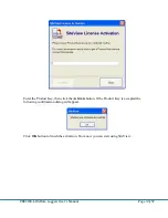
Страница 34: ...s Manual Page 33 57 Enter the Product Key then click the Activate button If the Product Key is accepted the following confirmation dialog will appear Click OK button to finish the activation From now...

Страница 35: ...logger connections to the computer For instance if the logger is connected to the computer via a USB port you need to use USB tab to communicate with the logger Menu Bar The Menu Bar contains File Vi...

Страница 36: ...urposes View Logger Status This manual will use USB as an example of communications interface For other communications interfaces please refer to SiteView User s Manual available for download online I...

Страница 37: ...d end time sampling interval and other properties of the connected logger General This sub tab page displays the general properties of the logger Alarm This sub tab page displays the properties regard...

Страница 38: ...ISE LOG Data Loggers User s Manual Page 37 57 WIFI This sub tab page displays the properties regarding the WIFI Through the tool bar buttons you can act on other tasks described in the following chapt...

Страница 39: ...ies of the logger and to start the new logging session If you are already in the logger status panel clicking on the Configure button will bring up the configuration dialog window There are three tab...

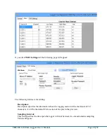
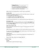
Страница 40: ...fields are for editing Description Description specifies the information about the logging session with a maximum of 30 characters It will be the default Title section of the plot in the plot view Sa...

Страница 41: ...his field to increase the battery life When Memory Full If you want the logger to stop logging when the memory is full select Stop logging If you want the logger to continue logging and overwrite the...

Страница 42: ...e values If you are recording the voltage output of a transducer or transmitter and the range of the voltage refers to another measurement unit you will need to create your own equation for this conve...

Страница 43: ...te by Alarm Enabled Check this field to associate this channel to the alarm state Low High Alarm These fields define the alarm thresholds If the reading is beyond these thresholds the alarm is trigger...

Страница 44: ...n amber to indicate it is trying to connect to the wifi network Once it successfully connected to the network it will stop amber blinking and return to the normal operation Once you have finished maki...

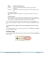
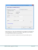
Страница 45: ...wnloaded to the system database Each data logger has a life time database file associated to it If you choose to Append Data to System Database you can specify End Time and start to download the data...

Страница 46: ...it or choose a file name Start Time End Time These fields specify the desired start and end time for the data to be downloaded You can use either scroll bars or the calendar controls to change the sta...

Страница 47: ...me display shows the list of the latest channel real time measurements as well as the trend chart of all channel real time measurements for the past given period of time from the current time To open...

Страница 48: ...PRECISE LOG Data Loggers User s Manual Page 47 57 Real Time in Horizontal View...

Страница 49: ...show hide the list view panel Chart View Visible Click to show hide the chart view panel Vertical View Click to display the chart and list views vertically Horizontal View Click to display the chart...

Страница 50: ...PRECISE LOG Data Loggers User s Manual Page 49 57 Dataset Click to display the tabular view of the recorded measurements illustrated below Settings Click to display more properties illustrated below...

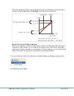
Страница 51: ...ut value is the lowest value for 0 5 VDC channel the lowest value is zero volt For instance if you apply zero volt input and the logger measured 100 as the digital value then Cali Low should be 100 di...

Страница 52: ...100 100 0 After Correction Max Value 65100 435 65535 Decide On Line or Off Line Calibration If the source signal like voltage or current can be connected to the logger while the logger is connecting t...

Страница 53: ...PRECISE LOG Data Loggers User s Manual Page 52 57 Select the channel you want to calibrate on and click OK button The calibration dialogs appear as follows...

Страница 54: ...PRECISE LOG Data Loggers User s Manual Page 53 57 The above dialogs are for On Line Calibration...

Страница 55: ...apter in SiteView User s Manual for details Communicate with PRECISE LOG Wirelessly Once you have configured the logger with correct WIFI propertied the logger will register with the WIFI network Then...

Страница 56: ...show the status window of the logger If the logger was not added to the USB Device Server tab please make sure the computer or router is not blocking port 48899 on UDP communication You can always add...

Страница 57: ...ons Interface USB Mini USB B USB A mini USB B Cable included WIFI module for W series Baud Rate 115200 bps Battery Power Built in 3 6V Lithium Battery Life Cycle 10 years based on 1 minute sampling in...

Страница 58: ...ED Indicator Tri Color LED can be disabled for power saving Normal Sampling green when sampling Alarm red when sampling Low Battery amber when sampling Operating Environment 40 70 C 40 to 158 F 0 95 R...

Отзывы: