


PIC16F87XA
DS39582B-page 148
2003 Microchip Technology Inc.
14.4
MCLR
PIC16F87XA devices have a noise filter in the MCLR
Reset path. The filter will detect and ignore small
pulses.
It should be noted that a WDT Reset does not drive
MCLR pin low.
The behavior of the ESD protection on the MCLR pin
differs from previous devices of this family. Voltages
applied to the pin that exceed its specification can
result in both Resets and current consumption outside
of device specification during the Reset event. For this
reason, Microchip recommends that the MCLR pin no
longer be tied directly to V
DD
. The use of an RCR
network, as shown in Figure 14-5, is suggested.
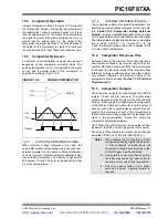
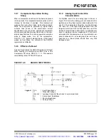
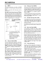
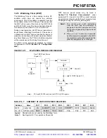
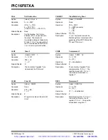
FIGURE 14-5:
RECOMMENDED MCLR
CIRCUIT
14.5
Power-on Reset (POR)
A Power-on Reset pulse is generated on-chip when
V
DD
rise is detected (in the range of 1.2V-1.7V). To take
advantage of the POR, tie the MCLR pin to V
DD
through an RC network, as described in Section 14.4
“MCLR”. A maximum rise time for V
DD
is specified.
See Section 17.0 “Electrical Characteristics” for
details.
When the device starts normal operation (exits the
Reset condition), device operating parameters (volt-
age, frequency, temperature, etc.) must be met to
ensure operation. If these conditions are not met, the
device must be held in Reset until the operating condi-
tions are met. Brown-out Reset may be used to meet
the start-up conditions. For additional information, refer
to application note, AN607, “Power-up Trouble
Shooting” (DS00607).
14.6
Power-up Timer (PWRT)
The Power-up Timer provides a fixed 72 ms nominal
time-out on power-up only from the POR. The Power-
up Timer operates on an internal RC oscillator. The
chip is kept in Reset as long as the PWRT is active. The
PWRT’s time delay allows V
DD
to rise to an acceptable
level. A configuration bit is provided to enable or
disable the PWRT.
The power-up time delay will vary from chip to chip due
to V
DD
, temperature and process variation. See
Section 17.0 “Electrical Characteristics” for details
(T
PWRT
, parameter #33).
14.7
Oscillator Start-up Timer (OST)
The Oscillator Start-up Timer (OST) provides a delay of
1024 oscillator cycles (from OSC1 input) after the
PWRT delay is over (if PWRT is enabled). This helps to
ensure that the crystal oscillator or resonator has
started and stabilized.
The OST time-out is invoked only for XT, LP and HS
modes and only on Power-on Reset or wake-up from
Sleep.
14.8
Brown-out Reset (BOR)
The configuration bit, BODEN, can enable or disable
the Brown-out Reset circuit. If V
DD
falls below V
BOR
(parameter D005, about 4V) for longer than T
BOR
(parameter #35, about 100
µ
S), the brown-out situation
will reset the device. If V
DD
falls below V
BOR
for less
than T
BOR
, a Reset may not occur.
Once the brown-out occurs, the device will remain in
Brown-out Reset until V
DD
rises above V
BOR
. The
Power-up Timer then keeps the device in Reset for
T
PWRT
(parameter #33, about 72 mS). If V
DD
should
fall below V
BOR
during T
PWRT
, the Brown-out Reset
process will restart when V
DD
rises above V
BOR
with
the Power-up Timer Reset. The Power-up Timer is
always enabled when the Brown-out Reset circuit is
enabled, regardless of the state of the PWRT
configuration bit.
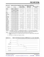
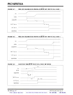
14.9
Time-out Sequence
On power-up, the time-out sequence is as follows: the
PWRT delay starts (if enabled) when a POR Reset
occurs. Then, OST starts counting 1024 oscillator
cycles when PWRT ends (LP, XT, HS). When the OST
ends, the device comes out of Reset.
If MCLR is kept low long enough, the time-outs will
expire. Bringing MCLR high will begin execution
immediately. This is useful for testing purposes or to
synchronize more than one PIC16F87XA device
operating in parallel.
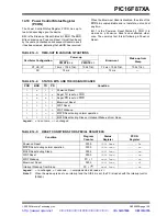
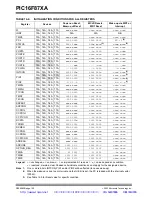
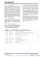
Table 14-5 shows the Reset conditions for the Status,
PCON and PC registers, while Table 14-6 shows the
Reset conditions for all the registers.
C1
R1
(1)
V
DD
MCLR
PIC16F87XA
R2
(2)
Note
1:
R1 < 40 k
Ω
is recommended to make
sure that the voltage drop across R does
not violate the device’s electrical
specification.
2:
R2 > than 1K will limit any current
flowing into MCLR from the external
capacitor C, in the event of MCLR/V
PP
breakdown due to Electrostatic
Discharge (ESD) or Electrical
Overstress (EOS).
http://www.xinpian.net
提供单片机解密、IC解密、芯片解密业务
010-62245566 13810019655
Содержание PIC16F87XA
Страница 112: ...PIC16F87XA DS39582B page 110 2003 Microchip Technology Inc NOTES http www xinpian net IC 010 62245566 13810019655...
Страница 128: ...PIC16F87XA DS39582B page 126 2003 Microchip Technology Inc NOTES http www xinpian net IC 010 62245566 13810019655...
Страница 136: ...PIC16F87XA DS39582B page 134 2003 Microchip Technology Inc NOTES http www xinpian net IC 010 62245566 13810019655...
Страница 168: ...PIC16F87XA DS39582B page 166 2003 Microchip Technology Inc NOTES http www xinpian net IC 010 62245566 13810019655...
Страница 174: ...PIC16F87XA DS39582B page 172 2003 Microchip Technology Inc NOTES http www xinpian net IC 010 62245566 13810019655...
Страница 198: ...PIC16F87XA DS39582B page 196 2003 Microchip Technology Inc NOTES http www xinpian net IC 010 62245566 13810019655...


