GUI Description
2018 Microchip Technology Inc.
DS50002834A-page 22
In the “Status and Control” bar the user can choose the hardware tool for the
communication with the device and the settings it should allow.
In order to connect to a device, the user must follow the steps described in
Section 2.3 “Getting Started”
. After connecting the Micro-USB cable,
the user must
scan for a valid address. Once a valid address is detected, clicking the
Connect
button
will initialize the connection with the device and the registers will be available for read
and write operations.
4.2.5
I
2
C Generic Register View
The I
2
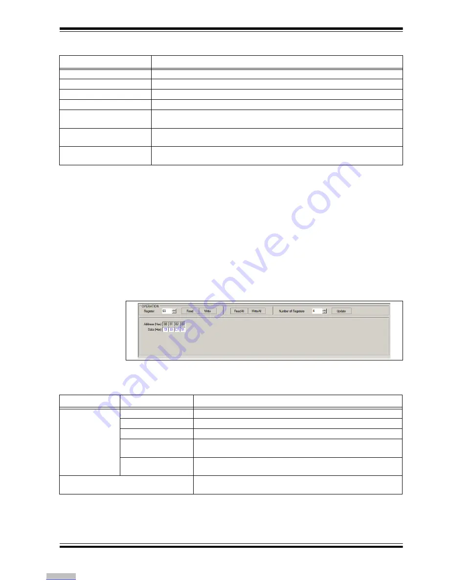
C Generic Register View area contains the items in
Table 4-2
. This section of the
I
2
C Monitor GUI is common for any device evaluated.
FIGURE 4-5:
Generic Register View Area.
The specific registers for MIC23356 are described in
Appendix C. “MIC23356
Internal Registers”
.
TABLE 4-1:
MONITOR STATUS AND CONTROL BAR
Item
Description
Addr
This drop-down menu shows the address of the available devices.
Connector
This drop-down menu shows the type of connector used to connect the board.
ScanAddr
This button is used to scan for a valid address.
Connect/Disconnect
These buttons are used to connect/disconnect the current selected device.
Voltage
This drop-down menu is used to select the voltage level of the communication when
using PICkit™ Serial Analyzer.
Rate
This drop-down menu is used to select the corresponding communication rate for the
device.
Pull Ups
This drop-down menu is used to activate the internal pull-ups from the PICkit Serial
Analyzer.
Note 1:
Optional. PICkit Serial Analyzer should first be connected on the I
2
C pin header, on the MIC23356 Evalu-
ation Board.
TABLE 4-2:
I
2
C GENERIC REGISTER VIEW ITEMS
Panel
Item
Description
Operation
Register
This section shows the registers available for read/write operations.
Read/Write
These buttons are used for single register read/write operations.
ReadAll/WriteAll
These buttons are used for reading/writing all the available registers.
Number of Registers
In this section, the user can set the number of available registers for
read/write operations.
Update
This button sets the number of available registers for read/write
operations in the register area.
Register area
This section shows the current status of the registers address and
their content.
Downloaded from
Downloaded from
Downloaded from
Downloaded from
Downloaded from
Downloaded from
Downloaded from
Downloaded from
Downloaded from
Downloaded from
Downloaded from
Downloaded from
Downloaded from
Downloaded from
Downloaded from
Downloaded from
Downloaded from
Downloaded from
Downloaded from
Downloaded from
Downloaded from
Downloaded from


