background image

MCP19117 Flyback Stand-Alone Evaluation Board User’s Guide

DS50002472A-page 28

 2016 Microchip Technology Inc.

3.2.3

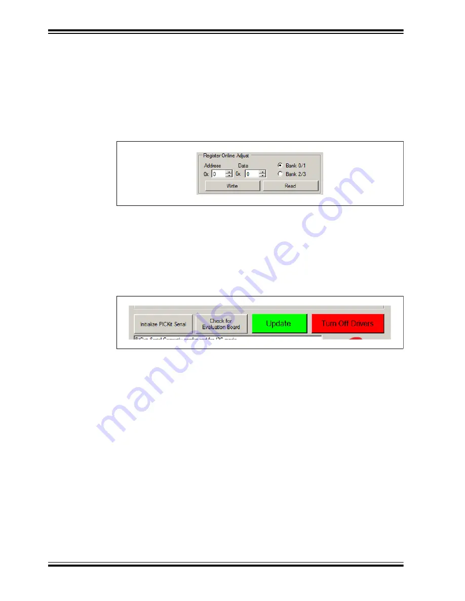
Register Online Adjust Area

The “Register Online Adjust” section of the GUI allows the user to have direct control 
of register values at any time when operating the MCP19117. The device data sheet 
contains information on register address locations and content. Reads and writes are 
done in hexadecimal format. Users must select the proper bank, which is especially 
important when executing a write. It is good practice to always execute an address read 
before a write, to check for expected results. This may help prevent an unintended write 
to an improper address or bank. Please note that the 

Update

 button will not update this 

section.

FIGURE 3-8:

Register Online Adjust Options.

3.2.4

Control Buttons Area

From left to right (see 

Figure 3-9

), the following four buttons are available:

• Initialize PICKit Serial 

button


(selectable self-test option)

• Check for Evaluation Board 

button


(selectable self-test option)

• Update 

button


• Turn Off Drivers 

button


FIGURE 3-9:

Control Buttons.

In this section the user can perform the following actions:
• Click the 

Initialize PICkit Serial

 button for the system to check the communica-

tion between your computer and PICkit Serial Analyzer. 

• Click the 

Check for Evaluation Board

 to manually ask the system to detect the 

evaluation board.

• Click the 

Update


button to apply the configuration settings made in “Operating 

Mode”, “Parameters”, “Protection”, “Switches Enable/Disable”, and “Advanced 
Register Update” areas. Clicking 

Update

 also turns on the output drivers. Note 

that it does not update information in the Register Online Adjust area.

• The 

Turn Off Drivers

 button is a master stop that shuts off the output drivers. 

Clicking this button disables both primary and secondary drivers. 

The system communicates whether the user action was successful or not in the Oper-
ating Status Box (see

 Figure 3-10

).

Содержание MCP19117

Страница 1: ...2016 Microchip Technology Inc DS50002472A MCP19117 Flyback Stand Alone Evaluation Board User s Guide...

Страница 2: ...rized access to your software or other copyrighted work you may have a right to sue for relief under that Act Microchip received ISO TS 16949 2009 certification for its worldwide headquarters design a...

Страница 3: ...2016 Microchip Technology Inc DS50002472A page 3 Object of Declaration MCP19117 Flyback Stand Alone Evaluation Board User s Guide...

Страница 4: ...MCP19117 Flyback Stand Alone Evaluation Board User s Guide DS50002472A page 4 2016 Microchip Technology Inc NOTES...

Страница 5: ...1 About the MCP19117 Flyback Stand Alone Evaluation Board 15 2 2 System and Configuration Requirements 15 2 3 Connecting Power Input and Output 16 2 4 Installing the MCP19117 Flyback Standalone GUI 1...

Страница 6: ...s Guide DS50002472A page 6 2016 Microchip Technology Inc A 4 Board Top Copper 34 A 5 Board Mid Layer 1 35 A 6 Board Mid Layer 2 36 A 7 Board Bottom Copper 37 A 8 Board Bottom Layer 38 Appendix B Bill...

Страница 7: ...Interface GUI Features Includes instructions on the MCP19117 Flyback Standalone GUI Appendix A Schematic and Layouts Shows the schematic and layout diagrams for the MCP19117 Flyback Stand Alone Evalua...

Страница 8: ...le Save Bold characters A dialog button Click OK A tab Click the Power tab N Rnnnn A number in verilog format where N is the total number of digits R is the radix and n is a digit 4 b0010 2 hF1 Text i...

Страница 9: ...s design resources user s guides and hardware support documents latest software releases and archived software General Technical Support Frequently Asked Questions FAQs technical support requests onli...

Страница 10: ...MCP19117 Flyback Stand Alone Evaluation Board User s Guide DS50002472A page 10 2016 Microchip Technology Inc NOTES...

Страница 11: ...ovides power to the internal analog circuitry and sup plies the reference voltage to the ADC This device features synchronous low side inte grated drivers and 8k Words non volatile memory all in a spa...

Страница 12: ...MCP19117 Flyback Stand Alone Evaluation Board User s Guide DS50002472A page 12 2016 Microchip Technology Inc FIGURE 1 1 Typical MCP19117 Flyback Application Two String LED Driver...

Страница 13: ...ontains headers for In Circuit Serial Programming ICSP as well as I2 C communication Several test points have been designed into the printed circuit board for easy access and development purposes The...

Страница 14: ...MCP19117 Flyback Stand Alone Evaluation Board User s Guide DS50002472A page 14 2016 Microchip Technology Inc NOTES...

Страница 15: ...The MCP19117 Flyback Stand Alone Evaluation Board is fully assembled pro grammed and tested to evaluate and demonstrate the MCP19117 operating perfor mance Users will need to download and install the...

Страница 16: ...GND Test Points as shown below Nominal VIN is 8V to 14V with the Positive terminal Red connected to VIN and the Negative terminal Black connected to GND FIGURE 2 1 Applying Power to the Board VOUT GND...

Страница 17: ...GUI 1 Download the MCP19117 Flyback Standalone GUI software package from the Microchip web site 2 Extract the content of the archive files on the computer 3 Double click the setup exe file to start s...

Страница 18: ...on the web page 3 Download the MCP19117 Flyback Stand Alone Firmware ADM00663_02_10403_U1 R2_Firmware zip from www microchip com mcp19117 under Documentation 4 Unzip the MCP19117 Flyback Stand Alone...

Страница 19: ...ware From the File menu select Open Project Figure 2 4 FIGURE 2 4 Opening Project in MPLAB X IDE 8 Browse for the location of the extracted firmware Select the MCP19117_Stand_Alone from the list then...

Страница 20: ...ochip Technology Inc 9 When the project is open click the Make and Program Device Main Project button on the tool bar to program the device Wait until the program process is complete see Figure 2 6 FI...

Страница 21: ...re required to launch the MCP19117 Flyback Standalone GUI 3 1 1 Prerequisites Prior to starting the GUI perform these actions 1 Apply an input voltage in the normal operating range 8V to 14V at the VI...

Страница 22: ...he GUI select Start All Programs Microchip Technology Inc MCP19117 FLYBACK_STANDALONE_GUI The interface detects the MCP19117 device automatically and is ready for use see Figure 3 2 FIGURE 3 2 MCP1911...

Страница 23: ...ivers and all the sections in the MCP19117 Flyback Standalone GUI become read only In order for the sections to become editable select the ON check box 3 2 1 2 OPERATING MODE SECTION The Operating Mod...

Страница 24: ...100 The Output Current can be adjusted within a range of 0 to 500 mA The Current Sense Resistor R6 value on the MCP19117 Flyback Stand Alone Evaluation Board is 200 m Both of these values are used to...

Страница 25: ...features must be selected Otherwise the protections are not applied The LED marked with D2 on the evaluation board is used to indicate various fault conditions The firmware will flash this LED to ind...

Страница 26: ...TION The Test Pin section of the GUI has a drop down menu that allows users to select and connect test signals to GPIO GPA0 These signals are accessible at the test point labeled TEST The Test Pin can...

Страница 27: ...a time period in nS for the Leading Edge Blanking PDRV Deadtime sets the delay time in nS for the primary driver SDRV Deadtime sets the delay time in nS for the secondary driver Input Current Offset...

Страница 28: ...wing four buttons are available Initialize PICKit Serial button selectable self test option Check for Evaluation Board button selectable self test option Update button Turn Off Drivers button FIGURE 3...

Страница 29: ...t the text box is blank It is populated when actions are performed in other sections of the GUI see Figure 3 10 The information is system generated and read only FIGURE 3 10 Operating Status Box The f...

Страница 30: ...MCP19117 Flyback Stand Alone Evaluation Board User s Guide DS50002472A page 30 2016 Microchip Technology Inc NOTES...

Страница 31: ...2A page 31 Appendix A Schematic and Layouts A 1 INTRODUCTION This appendix contains the following schematics and layouts for the MCP19117 Flyback Stand Alone Evaluation Board Board Schematic Board Top...

Страница 32: ...y H E E E E H E H H M M M M E y H E y M E H y H E P y H E H E H H H L M y L H E y 0 3 X 9 X 9 X 9 X 9 X 9 X 9 X 9 X 9 S 9 5 5 5 5 5 N N 5 5 N N 5 5 5 N X 9 13 X 9 13 X 9 13 X 9 13 X 9 13 S 9 S 9 N 5...

Страница 33: ...Schematic and Layouts 2016 Microchip Technology Inc DS50002472A page 33 A 3 BOARD TOP LAYER...

Страница 34: ...MCP19117 Flyback Stand Alone Evaluation Board User s Guide DS50002472A page 34 2016 Microchip Technology Inc A 4 BOARD TOP COPPER...

Страница 35: ...Schematic and Layouts 2016 Microchip Technology Inc DS50002472A page 35 A 5 BOARD MID LAYER 1...

Страница 36: ...MCP19117 Flyback Stand Alone Evaluation Board User s Guide DS50002472A page 36 2016 Microchip Technology Inc A 6 BOARD MID LAYER 2...

Страница 37: ...Schematic and Layouts 2016 Microchip Technology Inc DS50002472A page 37 A 7 BOARD BOTTOM COPPER...

Страница 38: ...MCP19117 Flyback Stand Alone Evaluation Board User s Guide DS50002472A page 38 2016 Microchip Technology Inc A 8 BOARD BOTTOM LAYER...

Страница 39: ...2K 1 C19 CAP CER 10000 pF 25V 10 X7R SMD 0603 Panasonic ECG ECJ 1VB1E103K 1 C20 CAP CER 1 F 25V 20 X5R SMD 0603 Panasonic ECG ECJ 1V41E105M 1 C21 CAP CER 0 1 F 50V 20 Y5V SMD 0603 AVX Corporation 0603...

Страница 40: ...ED Qty Reference Description Manufacturer Part Number Note 1 The components listed in this Bill of Materials are representative of the PCB assembly The released BOM used in manufacturing uses all RoHS...

Страница 41: ...Bill of Materials BOM 2016 Microchip Technology Inc DS50002472A page 41 NOTES...

Страница 42: ...86 24 2334 2829 Fax 86 24 2334 2393 China Shenzhen Tel 86 755 8864 2200 Fax 86 755 8203 1760 China Wuhan Tel 86 27 5980 5300 Fax 86 27 5980 5118 China Xian Tel 86 29 8833 7252 Fax 86 29 8833 7256 ASI...

Отзывы: