

MCP19111 PMBus™
PROTOCOL-ENABLED POL
CONVERTER REFERENCE DESIGN
USER’S GUIDE
2015 Microchip Technology Inc.
DS50002379A-page 21
Chapter 3. Calibration Procedure
3.1
INTRODUCTION
In order to increase the accuracy of the output voltage setting, output voltage
measurement and output current reading, a calibration procedure must be performed.
It is recommended to use the Microchip dedicated PMBMonitor GUI that can be
downloaded from the board’s web page, as it performs all needed computations and
greatly simplifies the procedures.
For more information on the mathematical basis and implementation of the calibration
procedures, refer to the
Appendix C. “Calibration Example”
.
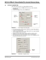
Figure 3-1
shows the PMBMonitor GUI Interface
Calibration
tab. It also identifies the
main panels used in the calibration procedures described in this chapter.
For more information on the Installation and Operation of the PMBMonitor GUI, refer to
the
“PMBus™ Monitoring Graphical User Interface User’s Guide”
(DS50002380).
FIGURE 3-1:
PMBMonitor GUI – Calibration Tab.
VOUT
Settings Panel
LOG
Text Box
STATUS Bar
Code
Label
IOUT
Settings Panel
Developer
Menu
Calibration
Tab