


Installation and Operation
2015 Microchip Technology Inc.
DS50002379A-page 19
2.2.3
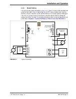
Board Testing
The typical testing setup is depicted in
Figure 2-1
.
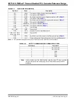
Table 2-1
shows all the available test
points on the board.
Table 2-2
describes the ICP/I
2
C communication pins’ function.
PROG on the J2 connector is used with the PICkit 3 in-circuit programmer/debugger.
The user can connect various instruments at the listed test points to evaluate the
parameters of the converter. The typical performance data, curves and waveforms are
presented in
Chapter 4. “Typical Performance Data, Curves and Waveforms”
.
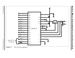
FIGURE 2-1:
Typical Test Setup.
USB
TP4
TP1
TP5
TP2
TP10
TP33
TP32
TP31
TP30
TP41
TP40
TP16
TP17
TP35
TP12
TP14
TP34
TP18
V
V
LOAD
Max
20A
ADJ
DC
PS
BODE PLOT
ANALYZER
A
B
J1
J2
ICP/I
2
C
PROG
+
-
+
-
TP3
RD1
RD2
RC1
RC2
BT1