background image

Theory of Operation

 2021 Microchip Technology Inc.

DS50003057A-page 33

performance is not degraded and the alarm automatically clears when the transient 

subsides. If the disturbance persists, and instrument performance may be 

compromised, the minor alarm (0x07) is promoted to a major alarm (0x07).

5.4

ZEEMAN SERVO

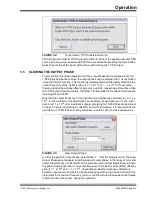
It is necessary to apply a magnetic bias field (the C-Field) to the RF interrogation region 

to prevent the other six transitions in the RF spectrum from interfering with the clock 

transition. To first order, the magnitude of this field has no (linear) effect on the 

frequency of the clock transition. There is, however, a second order shift of the clock 

transition given by:

EQUATION 5-1:

The Zeeman Frequency δv

Z

 is defined to be the splitting between adjacent hyperfine 

transitions and which varies linearly with the applied C-field. In the CsIII, the Zeeman 

frequency, δv

Z

 = 46,379.831 Hz, leading to a corrected clock frequency of v

C

 = 

9192631771.8720 Hz. Thus, the second-order Zeeman correction to the clock 

frequency is 1.872 Hz, about 2 parts in 10

10

. The C-field must be held stable to better 

than 30ppm in order to guarantee long-term stability of the CsIII at the level of 1 part in 

10

14

.

To stabilize the C-Field for long-term operation and in the presence of possibly 

changing external fields, the C-Field current is servoed to the atomic spectrum itself. 

Periodically, a measurement is made of the Ramsey fringe of the first Zeeman 

transition to the right of the clock transition, that is at v = v

C

 + δv

Z

 ±250 Hz. The 

measurement result is exponentially filtered and used to adjust the C-Field control 

voltage, which gently steers the C-Field current, so as to drive the Zeeman Ramsey 

error to zero. Monitor3 reports the Zeeman Ramsey error, that averages to zero in 

normal operation but may vary by ±10 mV depending on the presence of time-varying 

external fields. Monitor3 also reports the Zeeman Rabi error, that is measured at 

v = v

C

 + δv

Z

 ±5000 Hz. Because of the high sensitivity of the Zeeman transition to 

magnetic field, it is not unusual for the Zeeman Rabi error to be as high as ±75 mV, 

particularly in the presence of external magnetic fields near the instrument. If the 

Zeeman Rabi error exceeds 160 mV, it may indicate that the servo is locked to the 

wrong Ramsey fringe, leading to a clock offset of 5 parts in 1012. In this case, a major 

alarm (0x02) is declared and the CsIII attempts to reacquire the Zeeman servo. 

Monitor3 also reports the C-Field control voltage, that has a range of ±2.5 VDC and is 

set to 0 VDC prior to shipment, as well as the C-Field current, which is measured in mA 

and reported in the CBT Supplies section of the Monitor3 main panel. Typically, the 

C-Field current lies between 18.5 mA and 19.5 mA. If the C-Field current falls below 16 

mA or rises above 22 mA, a major alarm (0x05) is declared.

5.5

GAIN SERVO

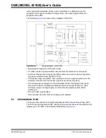
As the CBT ages, the signal level decreases and the level of background signal 

detected rises. The purpose of the gain servo is as follows:
• Guarantee that the resolution of the ADC is fully utilized
• Present consistent signal levels to the clock servo, and the other measurements 

and servos

V

C

V

0

8 V

0

 

V

Z

2

+

=

Where:

v

0

 = The unperturbed clock frequency (v

0

 = 9192631770 Hz)

δv

Z

 = The Zeeman frequency

Содержание 4310B

Страница 1: ...2021 Microchip Technology Inc Advance Information DS50003057A CSIII Model 4310B User s Guide...

Страница 2: ...icrochip are committed to continuously improving the code protection features of our products Attempts to break Microchip s code protection feature may be a violation of the Digital Millennium Copyrig...

Страница 3: ...specifications in product data sheet DS00003499 Appendix B Programmer s Guide This section describes the protocol for the RS 232 interface and includes general communication parameters and the com ma...

Страница 4: ...haracters A dialog button Click OK A tab Click the Power tab N Rnnnn A number in verilog format where N is the total number of digits R is the radix and n is a digit 4 b0010 2 hF1 Text in angle bracke...

Страница 5: ...chip Sales Department See www microsemi com sales contacts 0 for sales support contact information If you encounter any difficulties installing or using the product contact Microchip Frequency and Tim...

Страница 6: ...software General Technical Support Frequently Asked Questions FAQs technical support requests online discussion groups Microchip consultant program member listing Business of Microchip Product selecto...

Страница 7: ...ments and Information 5 The Microchip Website 6 Customer Support 6 Document Revision History 6 Chapter 1 Product Overview 9 1 1 Introduction 9 1 2 LED Indicators 9 1 3 Rear Panel Connections 9 1 4 Sof...

Страница 8: ...AT Shipping Considerations 24 4 5 Shipping Products Back to the Factory 24 4 6 Shipping Carriers 25 4 7 Storage 25 4 8 Cesium Beam Tube Vacuum 25 4 9 Cesium Beam Tube Shelf Life 25 Chapter 5 Theory of...

Страница 9: ...information see Appendix A Specifications 1 2 LED INDICATORS The following indicators are available on both the front and the rear panel Power Indicator Indicates power applied to instrument green LE...

Страница 10: ...requency or phase of outputs or to monitor internal health parameters In some applications users may develop their own inter face software for control and monitoring of the CsIII For more information...

Страница 11: ...The item number can be found on a label affixed to the rear panel Contact the Microchip distributor if the model or item numbers do not match 2 3 ENVIRONMENTAL CONSIDERATIONS When installing the inst...

Страница 12: ...e apply AC power to the CsIII by installing the detachable power supply cord at the AC Input connection on the rear panel Apply DC power to DC input if available Observe that the power and alarm front...

Страница 13: ...lication An uninstall icon is also added so that you can easily remove the program in the future For DB9 connector see the following table for connector pin out information 2 8 ESTABLISHING COMMUNICAT...

Страница 14: ...reen information every ten seconds The status bar in the lower left of the main window that reports count down to the next update and communication activity as it occurs indicates RS 232 sta tus In th...

Страница 15: ...l serial number and PC communication port The status bar at the bottom of the main window indicates RS 232 communication activity on the left and instrument status Warming Up Operating Minor Fault or...

Страница 16: ...in Note that the data is not saved if the specified directory does not exist The name for the data file may be entered into the Data Filename Template field The macro field ld is replaced with the ser...

Страница 17: ...ield C Field Current 19 17 21 mV 21 VuWave Microwave Power Control 1809 0 5000 mV 22 DCLevel DC Signal Level 2971 0 5000 mV 23 DACGain Digital Preamplifier Gain 2 61 0 255 mV 24 NumGain Numerical Gain...

Страница 18: ...reflecting the cur rent programmed offset of the CsIII in this case 1 x 10 13 To change the offset fre quency enter a new value between 999999 and 999999 into the edit field and click Apply Changes t...

Страница 19: ...including RF and 1PPS Note that the output frequency of the instrument is significantly perturbed by 1 x 10 9 for the duration of the adjustment For example phase advance of 1 ms intro duces a 1 x 10...

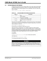
Страница 20: ...ndition ceases the instrument restarts from its initial power on condition The current list of alarms is indicated by hexadecimal code in the alarm list on the Monitor3 main panel To see an annotated...

Страница 21: ...of the alarm condition The time tag is composed of the date and time as realized by the CsIII event log clock and the total number of operating hours on the instrument 248 in the example above Becaus...

Страница 22: ...Loop Tau enter a new value between 0 1 and 99 9 seconds in the edit field and press the Apply Changes button 3 9 COMMUNICATIONS Upon delivery the CsIII communicates with the following serial interface...

Страница 23: ...edures are not required Do not disassemble components solely for the purpose of inspection During a component disconnection procedure such as a cable removal or replacement inspect components accordin...

Страница 24: ...ents no danger since the Cesium is encased within a vacuum sealed metal enclosure Hazardous materials depending upon their specific nature are subject to certain shipping regulations of the USDOT and...

Страница 25: ...ng companies for assistance If you need additional help contact customer support See contact listed in Appendix C Customer Assistance Technical Support Freight carriers typically request the following...

Страница 26: ...CSIII MODEL 4310B User s Guide DS50003057A page 26 2021 Microchip Technology Inc NOTES...

Страница 27: ...ovide a near ideal environment for continuously measuring the Cesium hyperfine transition All outputs of the CsIII are derived from an ovenized low phase noise 5 MHz quartz oscillator whose output fre...

Страница 28: ...um hyperfine frequency tunable around 9192631770 Hz The Cesium beam tube CBT which produces an error signal proportional to the detuning of the RF from the Cesium hyperfine resonance frequency The mic...

Страница 29: ...onstant temperature by the CBT power supply A collimator assembly at the output aperture of the oven forms a beam directed down the axis of the CBT An inhomogeneous magnetic field generated by the A m...

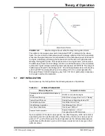
Страница 30: ...om the ADC In the CsIII interrogations are performed at a rate of 38 Hz and with a dwell time of 23 ms The Cesium atom possesses a nuclear spin of I 7 2 In its unperturbed ground state the nuclear spi...

Страница 31: ...CBT spectrum includes all seven allowed m 0 magnetic dipole transitions between the Zeeman sub levels of the two ground hyperfine states of Cesium With the exception of the central or Clock transition...

Страница 32: ...ge is symmetrically positioned atop the Rabi pedestal this value reads zero In the unlikely event that the clock servo has locked to the wrong peak of the Ramsey fringe producing a clock output error...

Страница 33: ...0 Hz The measurement result is exponentially filtered and used to adjust the C Field control voltage which gently steers the C Field current so as to drive the Zeeman Ramsey error to zero Monitor3 rep...

Страница 34: ...he function of the numerical gain is to present a consistent discriminator slope to the control servos independent of the signal or background levels or DAC gain adjustment The numerical gain is a flo...

Страница 35: ...5V In normal operation the Microwave Power Control Voltage may vary from 1 5V to 4V particularly in response to changes in ambient temperature 5 7 UNIT INITIALIZATION Upon power up the CsIII performs...

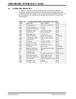
Страница 36: ...ec voltage 5 of factory setting Major 0x05 Cfield current 16 mA or 22 mA Major 0x06 EM voltage control 7 V or 13V Major 0x07 CBT signal quality Signal quality degraded Minor Major 0x08 VCXO tuning vol...

Страница 37: ...ear panel The following table lists the alarm connector pin out configuration A 2 OPTIONS Portability kit Includes handle and rubber feet p n 14959 101 DS1 Dual 1544 kbps outputs 1 balanced 1 unbalanc...

Страница 38: ...CSIII Model 4310B User s Guide DS50003057A page 38 2021 Microchip Technology Inc NOTES...

Страница 39: ...and list Note that this section is designed for experienced programmers and assumes a general knowledge of RS 232 interface programming B 1 GENERAL PARAMETERS The CsIII s factory default RS 232 settin...

Страница 40: ...eature that is not currently installed that is commands which address features particular to other Microchip Cesium instruments the CsIII performs no action and echoes the command back to the user wit...

Страница 41: ...relay cutoff No data required W18 Reserved for factory use W22 Arm 1PPS Sync circuit Issue this command after connecting a 1PPS source to the CsIII The sync remains armed for 3 seconds No data require...

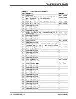
Страница 42: ...actory use A07 Reserved for factory use A08 Reserved for factory use A09 Reserved for factory use A10 Reserved for factory use A11 Reserved for factory use A12 Reserved for factory use A13 Reserved fo...

Страница 43: ...Clock pedestal servo voltage difference 91 98 RR 0045 Zeeman servo voltage difference 99 103 Z 008 Zeeman pedestal servo voltage difference 104 111 RZ 0004 Oscillator servo output voltage 112 118 AR...

Страница 44: ...CONSTANTS COMMAND D 2 Variable Field Example STX CR LF 1 3 Space 11 4 10 ID00025 Space 11 Day meter 12 14 006 Space 15 Time hour minute second 16 24 04h54mn32s Space 25 Spectrometer voltage nominal 2...

Страница 45: ...ttery backed up real time clock the Event log stores two distinct timestamps The first is a 6 byte calendar date the second is a 32 bit value representing the total system power on hours Zeeman offset...

Страница 46: ...CSIII Model 4310B User s Guide DS50003057A page 46 2021 Microchip Technology Inc NOTES...

Страница 47: ...rt This product contains the software with the latest version at the time of manufacture Refer to user guides and any system release notices from the website for the latest ver sions of software and i...

Страница 48: ...CSIII Model 4310B User s Guide DS50003057A page 48 2021 Microchip Technology Inc NOTES...

Страница 49: ...00 China Xian Tel 86 29 8833 7252 China Xiamen Tel 86 592 2388138 China Zhuhai Tel 86 756 3210040 ASIA PACIFIC India Bangalore Tel 91 80 3090 4444 India New Delhi Tel 91 11 4160 8631 India Pune Tel 91...

Отзывы: