15
OPERATION
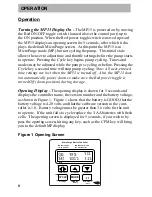
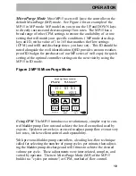
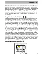
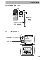
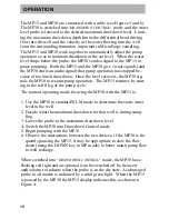
The MP15 and MP30 are connected with a cable (see Figures 5 and 6).
The MP30 is switched into
"DRAWDOWN CONTROL"
mode and the water
level probe is lowered to the desired maximum drawdown level. Limit-
ing the maximum drawdown depth limits the differential head driving
flow into the well and the velocity of the water flowing into the well
from the surrounding formation important in MicroPurge sampling.
The MP15 and MP30 work together to automatically adjust the pump
operation so as to maintain drawdown at the set level. When the water
level drops below the probe, the MP30 sends a signal to the MP15 to
pause pumping. Both the MP15 and the MP30 give visual signals (and
the MP30 emits an audio signal) that pump operation has stopped be-
cause of too much drawdown. Once the level recovers, the MP30 sig-
nals the MP10 to resume pump operation. The MP15 resumes by start-
ing in the refill leg of the pump cycle.
The normal operating mode for using the MP30 with the MP15 is:
1. Use the MP30 in standard WLM mode to determine the static water
level in the well
2. Decide what the maximum drawdown for that well is during samp-
ling
3. Lower the probe to the maximum drawdown level
4. Switch the MP30 into Drawdown Control mode
5. Begin pumping with the MP15
6. Observe the interactions between the two devices, if the MP30 is fre-
quently pausing the MP15, it may be appropriate to slow the flow
down (using the DOWN key in MP mode) to better match pump flow
to well recharge.
When switched into
"DRAWDOWN CONTROL"
mode, the MP30 has a
flashing red light and an optional (can be switched off by the user)
audio alarm to indicate when the probe is in the dry state. A submerged
probe in all modes is indicated by a solid green light. When the MP15
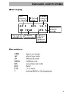
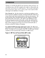
is paused by the MP30 the MP15 display indicates this as shown in
Figure 4.
Содержание MP15
Страница 2: ......

