RFT9709 Transmitter Instruction Manual
23
Wiring
continued
Wirin
g
Sta
rt
up
T
roub
lesh
ootin
g
Bef
o
re
Y
ou Be
gin
Mou
n
ting
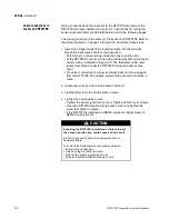
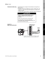
External zero switch wiring
The RFT9709 can be configured to allow flowmeter zeroing from an
external switch.
• The switch must be a momentary-type contact, normally open, and
must carry 1 mA of current in the closed position. The open circuit
voltage is 23 VDC.
• The flowmeter zeroing procedure is described in Section 3.2, page 27.
Figure 2-15.
Remote-zero switch wiring
WARNING
Failure to comply with requirements for intrinsic
safety in a hazardous area could result in an
explosion.
External zero switch wiring is not intrinsically safe.
Keep external zero switch wiring separated from
power-supply wiring, intrinsically safe sensor wiring, and
any other intrinsically safe wiring.
RFT9709 terminals
for output wiring
1
1
12 1
3
14 1
5
16
17
18
19
20
21 22
F GND (return)
ZERO+ (signal line)
Remote
switch
Terminal 18 is a common return for the frequency/pulse
output, the control output, and the external zero input.
09wire.fm Page 23 Monday, March 1, 1999 4:31 PM
Содержание Fisher-Rosemount RFT9709
Страница 1: ...Model RFT9709 Transmitter Instruction Manual March 1999 ...
Страница 2: ......
Страница 4: ......
Страница 8: ...iv RFT9709 Transmitter Instruction Manual ...
Страница 34: ...26 RFT9709 Transmitter Instruction Manual ...
Страница 52: ...44 RFT9709 Transmitter Instruction Manual ...
Страница 60: ...52 RFT9709 Transmitter Instruction Manual ...
Страница 62: ...54 RFT9709 Transmitter Instruction Manual ...
Страница 72: ...64 RFT9709 Transmitter Instruction Manual ...
Страница 73: ......


