18
RFT9709 Transmitter Instruction Manual
Wiring
continued
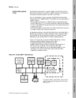
Primary and secondary
mA outputs
Primary and secondary output signals can be independently configured,
and can represent mass flow rate, gross volume flow rate, gross
standard volume flow rate, density, or temperature. With a pressure or
differential pressure transmitter, the primary and secondary output
signals can also represent pressure, differential pressure, or viscosity.
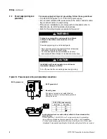
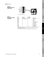
Figure 2-10.
mA output terminals
Output performance and requirements
• The mA outputs produce a 4-20 mA current, and can supply power for
loop-powered process indicators such as the Micro Motion PI 4-20
Process Indicator.
• Primary and secondary mA output loops are isolated and floating.
Additional grounding will result in optimum performance, and optimum
HART communication on the primary mA output. Ensure that mA
output loops are grounded at the external device.
• The maximum allowable length for mA signal wiring is determined by
measuring resistance over the signal wires and through the receiver
device. Total loop resistance must not exceed 1000 ohms.
Output fault setting
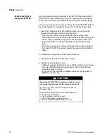
The mA outputs can be set to produce downscale or upscale fault levels.
• If set to downscale (switch 7 off), a fault drives the outputs to 0-2 mA
• If set to upscale (switch 7 on), a fault drives the outputs to 22-24 mA
Low-flow cutoffs
If an mA output is configured to represent a flow rate, flow values below
the user-defined low-flow cutoff cause the output to default to the level
that represents zero flow.
Slug-flow inhibit
The RFT9709 senses density outside user-selected limits. An mA output
configured to represent a flow rate holds at the last measured flow rate
before a slug-flow condition occurred, for a programmed time of 0-60
seconds, then defaults to the output level that represents zero flow.
Damping
A wide range of filter constants is available for damping on flow, density,
or temperature. Additional damping may be applied to mA outputs.
PV+ (signal line)
PV– (return)
SV+ (signal line)
SV– (return)
PV = Primary variable
SV = Secondary variable
RFT9709 terminals
for output wiring
11 1
2
13
14
15
16 17
18 19
20 2
1
22
09wire.fm Page 18 Monday, March 1, 1999 4:31 PM
Содержание Fisher-Rosemount RFT9709
Страница 1: ...Model RFT9709 Transmitter Instruction Manual March 1999 ...
Страница 2: ......
Страница 4: ......
Страница 8: ...iv RFT9709 Transmitter Instruction Manual ...
Страница 34: ...26 RFT9709 Transmitter Instruction Manual ...
Страница 52: ...44 RFT9709 Transmitter Instruction Manual ...
Страница 60: ...52 RFT9709 Transmitter Instruction Manual ...
Страница 62: ...54 RFT9709 Transmitter Instruction Manual ...
Страница 72: ...64 RFT9709 Transmitter Instruction Manual ...
Страница 73: ......

