


Micrel, Inc.
SY88147DL Evaluation Board
January 2006
3
M9999-011606-A
or (408) 955-1690
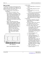
Setup for Measurements
This sub-section explains how to connect and setup the
SY88147DL evaluation board, per Figure 1. Always
ensure that proper ESD precautionary measures are
taken before handling sensitive electronic equipment,
including the SY88147DL evaluation board.
1. Set E3620A output to 3.3V and then turn off
E3620A. Connect E3620A’s positive lead to
V
CC
post, negative lead to GND post.
2. Configure Agilent BERT stack:
a. Set the 83752A Synthesized Sweeper to
1.25GHz.
b. From the 70004A’s Pattern menu, choose
the PRBS 2
23
–1 pattern.
c. From the 70004A’s Trigger menu:
i. Choose clock as trigger output
ii. Choose CLK/8 for divider
d. From the 70004A’s Data menu:
i. External Termination = DC termination
0V
ii. Attenuation = 40dB
iii.
Amplitude
=
5mV
PP
iv. Hi-Level = 0V
v. Tracking = ON
vi. Polarity = NORMAL
vii. Data Output = ON
viii.
Crossing
=
0
3. Connect 70843V’s trigger output to
86100A’s trigger input.
4. Use J1 to short /EN to GND on SY88147DL
evaluation board.
5. Connect DIN and /DIN on SY88147DL
evaluation board to 70843V’s data outputs
through 40dB attenuators
a. Connect 40dB attenuators directly to the
board rather than the 70843V’s data outputs
to allow a larger and cleaner signal to pass
through the connecting SMA cables.
6. Connect DOUT and /DOUT on SY88147DL
evaluation board to 86100A’s inputs.
7. Set DMM157 to display voltage. Connect
positive lead to LOS header on J1 and
connect negative lead to GND.
8. Turn on E3620A. Typical power supply
current should be ~45mA, including the
SY88147DL’s current and current through the
on-board 130
Ω
output pull-down resistors at
3.3V supply voltage. Excessive current
usually means the power supply leads have
been connected backwards. Be careful of this.
9. To configure 86100A oscilloscope:
a. Verify a trigger signal is present by
checking that the Trigger Source button is
lit.
i. Depress this button to choose
external source if necessary.
ii. Adjust trigger level if necessary.
b. Press Eye/Mask Mode on front panel.
c. Choose NRZ Eye Measurements from
on-screen display.
d. Choose RMS Jitter, Rise Time, Fall Time
and Eye Amplitude measurements from
on-screen selection list.


