


19
STRATA1
14.0 examples of calculating
flue pressure loss
0
29
31
33
35
37
39
41
43
45
47
49
51
53
55
57
59
61
63
65
67
69
71
73
50
100
200
150
250
300
350
400
450
500
Str
ata 1 - 75
Str
ata 1 - 60
Str
ata 1 - 45
0 2
6
10
14
18
22
26
30
34
38
0
10
30
50
70
90
110
130
20
40
60
80
100
120
140
4
8
16
12
20
24
28
32
36
40
example 1
A Strata 1-60 boiler is installed with a concentric flue
system which takes an all horizontal route to a wall
terminal. Length of flue = 3m including one 90° bend.
Resistance =
3 x 1m length 80/125 concentric tube @ 8.5 Pa = 25.5
1 x 90° 80/125 concentric bend @ 8.5 Pa = 8.5
1 x 80/125 concentric wall terminal @ 11.0 Pa = 11.0
Total Resistance = 45 Pa
conclusion:
Total resistance is less than 100 Pa,
therefore, no alternative design required and no effect on
boiler output, or positioning required.
example 2
A Strata 1-45 boiler is installed with a concentric flue
system which takes a part horizontal, part vertical route
to a roof terminal with rain cap.
Length of horizontal section = 3m, vertical section =
12m, system includes 3x90° bends.
Resistance =
15 x 1m lengths 80/125 concentric tube @ 5.5 Pa = 82.5
3 x 90° 80/125 concentric bend @ 5.5 Pa = 16.5
1 x 80/125 roof terminal @ 11.25 Pa = 11.25
Total Resistance - 110.25 Pa
Take into account that 12m of vertical (assume un-
insulated, as air for combustion direct from outside air
surrounds the flue gas tube) flue creates 20 Pa of
up-draught,
then final resistance = 110.25 - 20 = 90.25 Pa.
conclusion:
Final operating resistance is less than 100
Pa, therefore, no alternative design required and no effect
on boiler output.
example 3
A Strata 1-75 boiler is installed (non room sealed) with a
proposed flue using DN 80 PPS single skin flue
components which takes a part horizontal, part vertical
route to a vertical open termination with bird mesh.
Length of horizontal section = 4m, length of vertical (un-
insulated) section = 11m with 4 x 90° bends,
and 2 x 45° bends.
Resistance =
15 x 1m lengths DN 80 PPS tube @ 8.0 Pa = 120
4 x 90° DN 80 PPS bends @ 8.0 Pa = 32
2 x 45° DN 80 bends @ 4.0 Pa = 8.0
1 x DN 80 open termination @ 8.0 Pa = 8.0
Total Resistance: 168 Pa
Take into account that 11m of vertical un-insulated flue
creates 18 Pa of up-draught, then final resistance would
be 168 - 18 = 150 Pa.
Reference to the graph of resistance effect on boiler
output shows the output would be reduced to
approximately 67kW. If this is unacceptable, then the
flue resistance must be re-calculated using a larger size
flue tube as shown below or consideration given to
moving the boiler position.
Re-calculating proposed flue installation using DN100.
15 x 1m lengths DN 100 PPS tube @ 3.0 Pa = 45
4 x 90° DN 100 bends @ 3.0 Pa = 12
2 x 45° DN 100 bends @ 1.5 Pa = 3.0
1 x DN 100 open termination @ 4.0 Pa = 4.0
Total Resistance: 64 Pa
Take into account thermal up-draught created (as before)
18 Pa. Therefore, operating resistance = 64 - 18 = 46 Pa,
with no effect on boiler output.
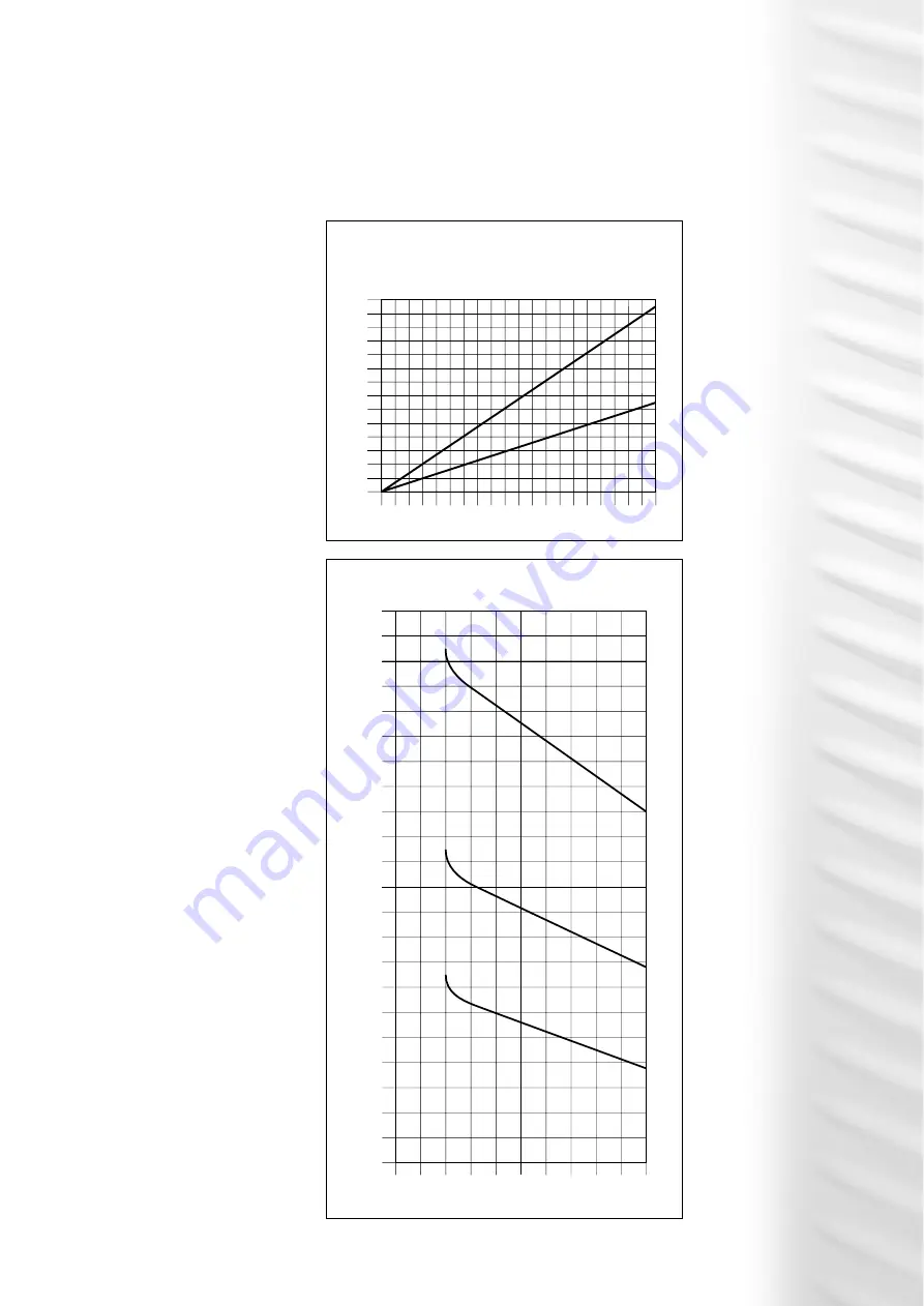
thermal up-draught when
flue gas temp 80°C and outside temp -5°C
effect of flue system resistance
on boiler output
Draught - P
a
Vertical Flue Lengths - metres
A = Insulated or within the building
B = Un-insulated and exterior to the building
A
B
Boiler Output kW at: Flow 80
°C Retur
n 60
°C
Flue System Resistance - Pa


