


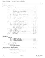


Section 3
Maintenance
section
description . . . . . . . . . . . . . . . . . . . . . . . . . . . . . . . . . . . . . . . . . . .page
3.0
Scope . . . . . . . . . . . . . . . . . . . . . . . . . . . . . . . . . . . . . . . . . . . . . .3 — 1
3.1
Preventive Maintenance . . . . . . . . . . . . . . . . . . . . . . . . . . . . . . . .3 — 1
Power-Sure™ 700 Performance Checklist . . . . . . . . . . . . . . . . . .3 — 2
3.2
Troubleshooting Guide . . . . . . . . . . . . . . . . . . . . . . . . . . . . . . . . 3 — 4
3.3
Troubleshooting Power Line and Electrical Connections . . . . . . .3 — 5
3.3.1
Step 1. Disassembling the Power Conditioners . . . . . . . . . . . . . .3 — 5
3.3.2
Step 2. Electrical Connections, Fuses . . . . . . . . . . . . . . . . . . . . .3 — 5
3.4
Checking the Power Modules (SCR) . . . . . . . . . . . . . . . . . . . . . .3 — 5
3.5
Check SCR Snubber Card . . . . . . . . . . . . . . . . . . . . . . . . . . . . . .3 — 6
3.5.1
Check Control Card and Filter Card . . . . . . . . . . . . . . . . . . . . . . .3 — 7
3.6
Final Testing and Adjustments . . . . . . . . . . . . . . . . . . . . . . . . . . .3 — 8
3.7
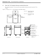
Unit Component Location Diagrams . . . . . . . . . . . . . . . . . . . . . .3 — 9
3.8
SCR Heat Sink Assemblies . . . . . . . . . . . . . . . . . . . . . . . . . . . .3 — 12
3.9
Field Adjustments of Circuit Cards . . . . . . . . . . . . . . . . . . . . . . .3 — 15
3.9.1
Power-Sure™ 700 Control Card #49120/407415 . . . . . . . . . . .3 — 15
3.9.2
Control Card Adjustment Procedure . . . . . . . . . . . . . . . . . . . . . .3 — 16
3.9.3
Over/Under Voltage Detection Board #35867 . . . . . . . . . . . . . .3 — 17
3.9.3.1 Undervoltage Adjustment . . . . . . . . . . . . . . . . . . . . . . .3 — 17
3.9.3.2 Overvoltage Adjustment . . . . . . . . . . . . . . . . . . . . . . . .3 — 17
3.9.3.3 Delay Adjustment . . . . . . . . . . . . . . . . . . . . . . . . . . . . .3 — 18
3.10
Manual Bypass Switch Option . . . . . . . . . . . . . . . . . . . . . . . . . .3 — 18
3.10.1 Normal Mode . . . . . . . . . . . . . . . . . . . . . . . . . . . . . . . . . . . . . . .3 — 18
3.10.2 Bypass Mode . . . . . . . . . . . . . . . . . . . . . . . . . . . . . . . . . . . . . . .3 — 18
3.10.3 Remote Emergency Power OFF (REPO) (Optional) . . . . . . . . .3 — 18
3.11
Replacement Parts . . . . . . . . . . . . . . . . . . . . . . . . . . . . . . . . . .3 — 19
3.12
Parts Numbers . . . . . . . . . . . . . . . . . . . . . . . . . . . . . . . . . . . . . .3 — 19
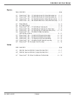
Appendices
Appendix A
A-1:
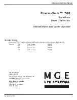
10-50kVA Wiring Diagram . . . . . . . . . . . . . . . . . . . . . . . . . . . . . .A — 1
A-2:
75-150kVA Wiring Diagram . . . . . . . . . . . . . . . . . . . . . . . . . . . . .A — 2
A-3:
125-300kVA Wiring Diagram . . . . . . . . . . . . . . . . . . . . . . . . . . . .A — 3
MGE Warranty & Propriety Rights
. . . . . . . . . . . . . . . . . . . . . . . . . . . . . . . . . . . . . . . .W — 1
MGE Warranty
Proprietary Rights Statement
Technical Support and Field Service
. . . . . . . . . . . . . . . . . . . . . . . . . . . . . . . . . . . . . .W — 3
MGE Service and Repair
Who to Contact
Scheduling Field Service Engineer Support
Return for Repair (RMA)
Contents
Power-Sure™ 700 —
Three Phase Power Conditioners
c ii
86-108814-00 B01
Содержание POWER-SURE 700
Страница 1: ...Three Phase Power Conditioners Installation and User Manual w w w m g e u p s c o m Power Sure ...
Страница 6: ... This page left blank intentionally Power Sure 700 Three Phase Power Conditioners vi 86 108814 00 B01 ...
Страница 10: ... This page left blank intentionally Power Sure 700 Three Phase Power Conditioners c iv 86 108814 00 B01 ...
Страница 46: ... This page left blank intentionally Power Sure 700 Three Phase Power Conditioners A 4 86 108814 00 B01 ...
Страница 49: ......
Страница 50: ......
Страница 51: ......


