

Installation and Operation
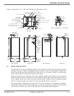
Power-Sure™ 700 —
Three Phase Power Conditioners
2 — 6
86-108814-00 B01
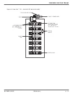
As the input voltage (building power) varies, the voltage available at each tap of the transformer will also change.
The amount of variation is dependent upon the input sag or surge, turns ratio and transformer losses.
By selecting a particular tap voltage, the output can be kept within a tight range. The way in which this is accom-
plished is that an electronic control card using a micro-processor continually monitors the input voltage. When a
voltage fluctuation occurs, which exceeds the limit of rated regulation (typically ± 3%), the output is switched to
another tap, that is within the required range. This switch will be made at the next current zero crossing to allow for
both leading and lagging power loads to be connected to the conditioner.
2.5
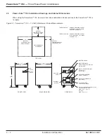
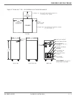
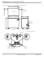
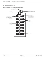
Power-Sure™ 700 Cable Connections
2.5.1
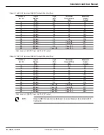
Input Wire Size, Grounding, and Output Wiring
◗
Conduit should be used for both input and output wiring.
◗
Minimum ground wire size is based on 1990 Nation Electric Code Table 250-95.
◗
Input wire size is based on 1990 NEC Table 310-16 specifying not more than 3 conductors in a raceway
based on ambient of 30 degrees Celsius, and wire rated at 75 degrees Celsius.
◗
Output neutral to ground is already bonded during manufacturing of Power Conditioner.
◗
Output requires 4 (5 including ground wire) conductors in a raceway assuming neutral as a current carry-
ing conductor. This requires conductors to be derated by using a multiplier of .8, reference 1990 NEC
Article 310 Section 8A.
Example:
1.
Assume #10 wire max current = 25 Amps.
2.
Multiply 25 x .8 = 20.
3.
20 Amps is max current for #10 wire in a raceway with 4 conductors.
NOTE:
Installation is subject to local codes – verify with a local electrical inspector.
Содержание POWER-SURE 700
Страница 1: ...Three Phase Power Conditioners Installation and User Manual w w w m g e u p s c o m Power Sure ...
Страница 6: ... This page left blank intentionally Power Sure 700 Three Phase Power Conditioners vi 86 108814 00 B01 ...
Страница 10: ... This page left blank intentionally Power Sure 700 Three Phase Power Conditioners c iv 86 108814 00 B01 ...
Страница 46: ... This page left blank intentionally Power Sure 700 Three Phase Power Conditioners A 4 86 108814 00 B01 ...
Страница 49: ......
Страница 50: ......
Страница 51: ......


