background image

Comet installation and user manual: E-6761200XT/FA

Merlin Gerin by MGE UPS SYSTEMS

1.1

introduction to Comet

safety information

A configuration sheet, included with the UPS, indicates all the factory settings.
Keep the sheet in a safe place as it may be required by the after-sales support
technicians if you wish to modify parameters.

Danger: high voltages are present inside the Comet system. Any servicing
requiring removal of the protection covers may be undertaken only by qualified
personnel certified by MGE UPS SYSTEMS.

Read the label (figure 1) on the back of Comet or inside the door to familiarise
yourself with the characteristics of your UPS.

identification to Comet

(1)Comet model number:

S11 (series 11): single-phase input power and single-phase load;

S31 (series 31): three-phase input power and single-phase load;

S33 (series 33): three-phase input power and three-phase load.

Fig. 1

Identification plate

configuration

comet  S.

(1)

RESEAU 1 - MAINS 1 - NETZ 1

RESEAU 2 - MAINS 2 - NETZ 2

UTILISATION  - LOAD - AUSG

Mains 1 characteristics 
(AC input)

Mains 2 characteristics
(optional AC bypass
input)

load characteristics

serial number

MERLIN GERIN

4

3

2

1

Содержание Comet TM 5 - 30 kVA

Страница 1: ...Comet 5 30 kVA MERLIN GERIN fault MERLIN GERIN comet BY MGE UPS SYSTEMS B Y M G E U P S S Y S T E M S E 6761200XT FC installation and user manual...

Страница 2: ...id environment Comet must be protected from penetration by liquids or extraneous objects ventilation grates must remain free Comet must not be placed in direct sunlight or near a heat source Comet con...

Страница 3: ...ere For unng forstyrrelser kan begrensninger i f m installasjon eller ytterligere sikkerhetstiltak v re n dvendig c advarsel Comet er forsynet med indbyggede eller eksternt tilsluttede batterier Udsty...

Страница 4: ...itar a penetra o de qualquer l quido ou objectos estranhos para o interior do Comet n o obstruir as grelhas de ventila o do Comet n o colocar o Comet exposi o do sol ou junto de uma fonte de calor o C...

Страница 5: ...k koskaan antako nesteiden tai vieraiden esineiden p st Cometin sis lle lk koskaan peitt k Cometin ilmanvaihtoristikkoa lk asettako laitetta suoraan auringonvaloon tai l mm l hteen l helle Comet sis l...

Страница 6: ...i Comet t ck aldrig f r Comets ventilationsgaller placera aldrig Comet i direkt solljus eller i n rheten av en v rmek lla Comet har ett kapslat batteri med blyelement Dessa f r endast sl ngas i enligh...

Страница 7: ...ecial precautions 2 2 connections 2 2 basic controls and indications 3 1 controls and diagnostics display 3 4 preliminary checks 4 1 powering up 4 1 inverter start up 4 2 inverter shutdown 5 1 powerin...

Страница 8: ...eral characteristics 11 4 selection of cable cross sections 11 5 selection of protection devices 11 6 connection of cable shielding 11 8 12 1 maintenance and servicing options glossary Comet and the o...

Страница 9: ...nly by qualified personnel certified by MGE UPS SYSTEMS Read the label figure 1 on the back of Comet or inside the door to familiarise yourself with the characteristics of your UPS identification to C...

Страница 10: ...uit breaker switch and fuse for 5 kVA Comet S11 or S31 5 battery 6 charger module 7 inverter module 8 manual maintenance bypass switch 9 basic control and indication panel 10 special command and diagn...

Страница 11: ...interval is not respected battery life is extended when it is installed in a room with an ambient temperature of 15 to 25 C Above 25 C battery life reduced by 50 for every additional 10 C heat loss re...

Страница 12: ...onditions are not respected maintenance and servicing of the unit may require system shutdown load cables must be run separately from all other cables power supply or computer system interconnection c...

Страница 13: ...stalled upstream on the low voltage switchboard is in off O position check that the input power switch 1 and the battery circuit breaker 4 are in off O position Connection sequence for 5 kVA Comet ope...

Страница 14: ...ase earth from LV switchboard three phases neutral and earth XR3 battery optional XR2 load XR1 Mains 1 XR1 Mains 2 optional see the paragraph on connection of the cable shielding in the section append...

Страница 15: ...cting the earth neutral and phase correspondence as indicated on the label connect the various options as indicated in the corresponding sections of this manual once the cables have been connected eac...

Страница 16: ...30kVA Fig 13 Fig 14 to load single phase earth from LV switchboard three phases neutral and earth XR3 battery optional XR2 load XR1 Mains 1 XR1 Mains 2 optional L1 N L L1 N L N L1 L2 L3 to load three...

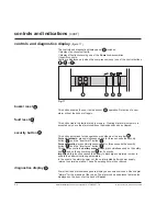
Страница 17: ...r left hand corner of the front panel this panel provides information on the operating status of the system see figure 16 Interpretation of signals is very easy and requires no special training They i...

Страница 18: ...erload or an internal fault battery power is not available because the battery circuit breaker 4 is in off position This orange light indicates inverter 7 operation on battery power following an AC in...

Страница 19: ...g inverter operation on battery power When the low battery shutdown warning level has been reached the level and the frequency of the beeps increases In the event of an inverter shutdown a continuous...

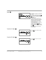
Страница 20: ...he inverter on button 22 This key also controls a battery manual test press simultaneously on the safety key 26 and on the buzzer stop key 24 for 3 seconds Important this function causes the battery t...

Страница 21: ...er on the low voltage switchboard in on position the load is supplied via the static bypass 3 No indications are given on the control panel BY PASS NORMAL TEST 2 TEST 1 manual maintenance bypass switc...

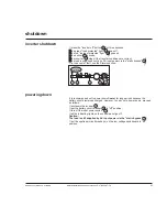
Страница 22: ...n In the event of a fault the red load not protected light goes on See the alarms section start up cont 21 I O 22 18 inverter start up system in manual start up mode press the green inverter on button...

Страница 23: ...e event of fault see the Alarms section inverter shutdown bip bip 21 I O 23 18 17 powering down It is recommended not to power down Comet for long periods because the battery should remained charged H...

Страница 24: ...5 2 Comet installation and user manual E 6761200XT FA Merlin Gerin by MGE UPS SYSTEMS...

Страница 25: ...charger is temperature regulated to ensure an optimal charge voltage I O 21 When AC input power fails or exceeds tolerances the rectifier 2 and the charger 6 shut down The battery 5 supplies the power...

Страница 26: ...with a communications option A low battery shutdown warning signal is available via the standard communication connector 15 for remote indications It warns the user of upcoming battery shutdown at a...

Страница 27: ...1 7 1 9 2 1 mn time overload except for 5 kVA Comet S11 or S31 during a major temporary overload greater than 1 5In the load is supplied by AC input power via the static bypass 3 return to the invert...

Страница 28: ...applied to the rated current and therefore to the overload curve in figure 21 from 30 C to 35 C k 0 9 from 35 C to 40 C k 0 85 above 40 C k 0 8 Example an overload current I can be supplied by the in...

Страница 29: ...s 1 as option Mains 2 can be connected to a separate terminal block the voltage tolerance of Mains 2 is defined with respect to the UPS rated output voltage and is 7 10 for rated voltages of 240V and...

Страница 30: ...6 6 Comet installation and user manual E 6761200XT FA Merlin Gerin by MGE UPS SYSTEMS...

Страница 31: ...er The inverter on button 22 has been pressed normal operation load supplied by Comet inverter 7 shutdown following pressing of the inverter off button 23 or a major fault load supplied via the static...

Страница 32: ...maintenance in the maintenance and servicing section 16 ambient T fault this display indicates that the ambient temperature is outside the tolerance range 0 C or 40 C 17 battery periodic test this me...

Страница 33: ...olerance range 39 installation fault indicates an incorrect connection at the frequency converter input check the connection of the Mains 1 input source to terminal block XR1 41 load supplied via stat...

Страница 34: ...e The TEST 1 and TEST 2 positions are reserved for the after sales support personnel Leave the switch set to the BYPASS position until the arrival of the after sales support personnel Use of the switc...

Страница 35: ...n with the most common computer systems AS400 NOVELL etc Figure 25 indicates the pin outs for the SUB D 15 pin female connector front view SUB D 15 pin connector connection 4 14 12 7 13 11 9 10 6 8 5...

Страница 36: ...the inverter general alarm Relay contact breaking capacities 250V AC 125V DC 1A This option manages an RS232 serial interface using an ASCII protocol This option is supplied with the CD ROM Solution...

Страница 37: ...tion on battery light 20 flashes and fault number 12 is indicated on the diagnostics display 27 the battery should be checked When the red load not protected light 18 flashes and fault number 15 is in...

Страница 38: ...s offered by MGE UPS SYSTEMS enable personnel to monitor the system and undertake basic maintenance Contact your MGE UPS SYSTEMS distributor for the list of courses offered Your MGE UPS SYSTEMS contac...

Страница 39: ...11 height mm 730 910 910 width mm 360 400 400 depth mm 420 550 550 weight kg 72 118 149 series 31 height mm 730 910 910 1085 1085 width mm 360 400 400 560 560 depth mm 420 550 550 680 680 weight kg 72...

Страница 40: ...he yellow green terminal on XR3 red cable pole to the L terminal on XR3 blue cable pole to the L terminal on XR3 position the two enclosures with the front panels aligned turn on the circuit breaker i...

Страница 41: ...ion of an MX shunt trip check that the upstream circuit breaker on the low voltage switchboard is in off position check that the input power switch 1 and the battery circuit breaker 4 are in off posit...

Страница 42: ...een the low voltage switchboard and the input power switch for Comet series 11 and series 33 see figure 26 between the Comet load output terminals and the load for Comet series 31 see figure 27 The ca...

Страница 43: ...rmation on cable cross sections see the appendices selection of cable cross sections the connection cable between Comet and the option is supplied power connection diagram load Mains 1 XR2 XR1 Comet M...

Страница 44: ...ed with a separate Mains 2 This option is delivered either with or without a battery The cables requiring connection are indicated as bold lines For information on cable cross sections see the Appendi...

Страница 45: ...or the separate Mains 2 option on the standby Comet see the separate Mains 2 section above The cables requiring connection are indicated as bold lines For information on cable cross sections see the a...

Страница 46: ...and series 33 units with a rated output at least equal to 15kVA The cables requiring connection are indicated as bold lines For information on cable cross sections see the appendices selection of cabl...

Страница 47: ...of Comet from Mains 1 the two options full isolation transformer and separate Mains 2 transformer must be combined Each option requires its own cubicle Example of a Comet series 31 The two options ar...

Страница 48: ...le separate Mains 2 transformer and harmonics filter Comet D1 XR1 Mains 1 XR8 D2 XR1 Mains 2 XR7 XR6 LV switchboard XR4 XR5 No connections are to be made to terminal block XR8 If several option cubicl...

Страница 49: ...ept where indicated the data provided are typical values corresponding to a rated single phase voltage of 230V and a rated three phase voltage of 400V a linear rated load with a power factor of 0 8 ra...

Страница 50: ...rrent mA directly earthed neutral system TT 10 23 23 during a fault with an impedent neutral system 28 60 60 dimensions and weight height mm 730 910 910 width mm 360 400 400 depth mm 420 550 550 weigh...

Страница 51: ...eakage current mA directly earthed neutral system TT 5 11 11 24 24 during a fault with an impedent neutral system 23 45 45 102 102 dimensions and weight height mm 730 910 910 1085 1085 width mm 360 40...

Страница 52: ...urrent mA directly earthed neutral system TT 23 23 23 23 during a fault with an impedent neutral system 90 90 250 250 dimensions and weight height mm 1085 1085 1385 1385 width mm 460 460 610 610 depth...

Страница 53: ...current XR2 XR3 series 11 5 26 23 30 7 5 40 35 48 10 52 46 46 series 31 1 5 23 9 23 30 7 5 35 14 35 48 10 46 18 46 46 15 69 27 69 76 20 91 36 91 75 series 33 2 10 18 26 15 26 46 15 27 40 23 40 76 20 3...

Страница 54: ...C60N 50A curve D C60N 10A curve B 15 NC100H 80A curve D C60N 25A curve B 20 NC100H 100A curve D C60N 25A curve B series 33 10 C60N 40A curve D C60L 6A curve Z or C60N 6A curve B 15 C60N 40A curve D C...

Страница 55: ...rlin Gerin Merlin Gerin output kVA circuit breaker CB1 circuit breaker CB1 Mains 1 Mains 2 series 31 5 C60N 10A curve D C60N 25A curve D 7 5 C60N 16A curve D C60N 40A curve D 10 C60N 20A curve D C60N...

Страница 56: ...ires into the cylinder and keep the cable shielding outside the cylinder tie the cable shielding to the cylinder behind its shouldered part connect the wires to the corresponding terminal block put th...

Страница 57: ...ransfer to bypass load switching from the inverter to the static bypass battery circuit breaker DC power circuit breaker that protects the battery circuit fused switch for 5 kVA Comet S11 or S31 low b...

Страница 58: ...wer drawn by the load in excess of the Comet rated output LV switchboard low voltage switchboard upstream from Comet transfer load switching from static bypass to the inverter or vice versa load all d...

Страница 59: ...Merlin Gerin by MGE UPS SYSTEMS 6761200XT...

Страница 60: ...markets Merlin Gerin brand UPSs As standard specifications and designs change from time to time please ask for confirmation of the information given in this publication Product names mentioned herein...

Отзывы: