MFJ-5124K/Y Radio Interface
Instruction Manual
©
2005-2006 MFJ Enterprises, Inc.
1
Introduction
The MFJ-5124 Radio Interface main unit contains all the electronics that allows
users of AT-300 compatible Kenwood transceivers, FC-30 compatible Yaesu
transceivers, and certain Yaesu transceivers with supported CAT system to
connect to the MFJ-991, MFJ-993 and MFJ-994
IntelliTuner™
Automatic
Antenna Tuners. With this interface, DC power to the radio interface and the
tuner is supplied by the radio, except FT-847 CAT. Using the appropriate cable
and selecting the interface protocol via internal jumpers allow one-button
automatic tuning operation with various Kenwood and Yaesu transceivers.
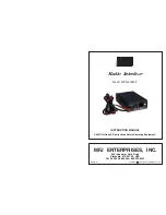
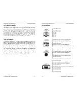
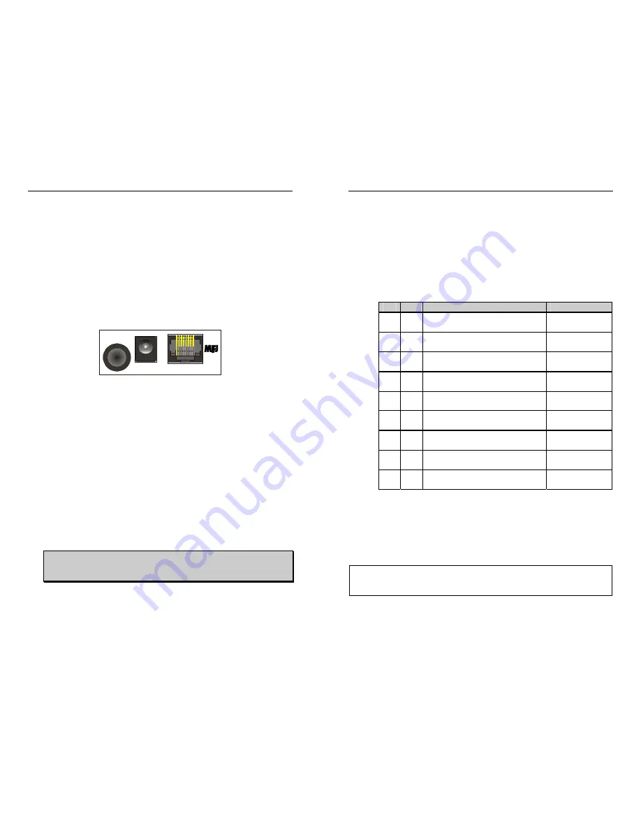
Front Panel
MFJ-5124
Radio Interface
POWER
TO RADIO
TO TUNER
•
To Tuner:
The 3.5 mm stereo phone plug connects to the tuner’s RADIO
INTERFACE jack, and the 2.1 × 5.5 mm coaxial plug connects to the
tuner’s POWER jack.
•
Power:
Accepts a standard 2.1 × 5.5 mm coaxial plug with positive center
and negative sleeve. The tuner requires 12 volts DC at up to 1 amp. The
use of a regulated supply is not mandatory but is recommended for best
performance. An optional 12 volts DC 1.5 amp power supply, the MFJ-
1316, is available from MFJ Enterprises, Inc.
Most radios p13.8 volts through the radio’s tuner port (Kenwood
AT/ACC or Yaesu CAT/LINEAR) to the TO RADIO jack, so the POWER
jack connection is rarely used. If the radio’s tuner port does not have a
power connection, such as the Yaesu FT-847 CAT connector, then connect
a power supply to this connector. If the radio’s tuner port has a power
connection but cannot supply one amp of current, then remove the internal
jumper JP3 and connect a power supply to this connector. Check your
radio’s operating manual.
WARNING:
Do not apply voltages greater than 18 volts to this
unit, or permanent damage to the unit and the tuner
may result.
•
To Radio:
Accepts an 8-pin modular plug that connects the radio interface
to a Kenwood AT/ACC or Yaesu CAT/LINEAR connector. Use proper
cable for the various radios.
MFJ-5124K/Y Radio Interface
Instruction Manual
2
©
2005-2006 MFJ Enterprises, Inc.
Jumper Settings
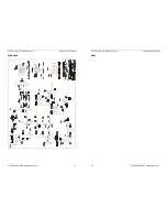
Two jumpers, JP1 and JP2, inside the MFJ-5124 are used to select the radio to
interface with. To change these jumper settings:
1. Disconnect the MFJ-5124 from the radio and the tuner.
2. Open the MFJ-5124 case by removing the two screws on the bottom.
3. Configure jumpers JP1 and JP2 according to the following table to
select the radio to interface with.
JP1 JP2
To Interface
Using
A A
Kenwood (auto detected tuner)
†
such as TS-570S, etc.
MFJ-5124K
(6-pin molex)
A B
Kenwood (menu enabled tuner)
such as TS-450S, TS-690S, etc.
MFJ-5124K
(6-pin molex)
A
C
Firmware Version Number
N/A
B A
Yaesu TUNER interface
‡
FT-100, FT-857, FT-897
MFJ-5124Y
(8-pin mini DIN)
B
B
Reserved for future use.
N/A
B
C
Reserved for future use.
N/A
C A
Yaesu CAT interface
FT-100
MFJ-5124Y
(8-pin mini DIN)
C B
Yaesu CAT interface
FT-857, FT-897
MFJ-5124Y
(8-pin mini DIN)
C C
Yaesu CAT interface
§
FT-847
MFJ-5124Y2
(DB-9)
† MFJ-5124K factory default.
‡ MFJ-5124Y factory default.
§
MFJ-5124Y2 factory default.
4. Close the MFJ-5124 case and secure with the two screws.
5. Refer to the appropriate section in this manual to connect the MFJ-5124
to the radio and the tuner.
Note:
The Yaesu TUNER interface allows the use of the
radio’s
(TUNE)
key to initiate automatic tuning, whereas the Yaesu CAT interface
uses the
tuner’s
[TUNE] button to start automatic tuning.

