MFJ-998 Legal Limit IntelliTuner Automatic Antenna Tuner
Instruction Manual
©
2007-2010 MFJ Enterprises, Inc.
10
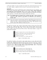
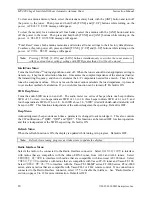
to CW mode, transmit a low power (typically 10-30 watt) carrier, and start the tuning process. Once
the automatic tuning is completed, the radio will return to its previous mode and power setting.
Jumper JP1
There is a jumper JP1 inside the MFJ-998 that must be configured properly when interfacing to the
various radios. Normally this jumper is installed and is the factory default.
Remove this jumper
when interfacing to an Icom IC-7000.
Make sure this jumper is installed when interfacing to
Kenwood radios and FC-30 compatible Yaesu radios using the MFJ-5114K and MFJ-5114Y interface
cables, respectively. For the other radios, the position of jumper JP1 is irrelevant.
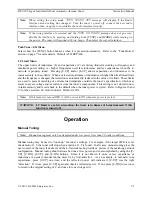
Note: The MFJ-998 must be powered from a separate DC source. Power from the
accessory or tuner connector is not passed to the MFJ-998 via the transceiver
interface cable.
Note: If the wrong interface is selected and the
TURN ON RADIO
message does not go away,
disable the interface by pressing and holding both [TUNE] and [MODE] buttons while
turning on the power. The tuner will respond with two beeps. Then select the correct
interface using the MFJ-998 Radio Interface setup mode.
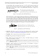
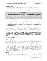
The MFJ-5114A interface cable provides control signals between an Alinco radio and the MFJ
automatic tuner. Supported Alinco radios are DX-70, DX-77, DX-701, DX-801, and any Alinco
radio that supports the Alinco EDX-2 tuner. Press the radio’s [TUNE] button to start the tuning
process; for DX-70 press [FUNC] then [TUNE]. Refer to “Alinco Radio Interface” on page 32 for
connections and operation.
Pin 1 (Ground) connects to pins 4 and 5 of Radio Interface Plug.
Pin 2 (+13.8V) connects to pins 2 and 3 of Radio Interface Plug.
Pin 3 (Key) connects to pin 6 of Radio Interface Plug.
Pin 4 is not connected.
Pin 5 (Start) connects to pin 8 of Radio Interface Plug.
5
1
2
3
4
Figure 6. Alinco Interface Cable.
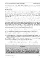
The MFJ-5114I interface cable provides control signals between an Icom radio and the MFJ
automatic tuner. Supported Icom radios are IC-706, IC-707, IC-718, IC-725, IC-728, IC-736, IC-738,
IC-746, IC-756, IC-7000, and any Icom radio that supports the Icom AH-3 or AH-4 tuner. Push and
hold the radio’s [TUNER] button for two seconds to start the tuning process. Push [TUNER] quickly
to bypass the tuner.
Make sure jumper JP1 is removed for IC-7000.
Refer to “Icom Radio
Interface” on page 33 for connections and operation.
Pin (Key) connects to pin 6 of Radio Interface Plu
Pin (Start) connects to pin 8 of Radio Interface Plug.
Pin (Ground) connects to pins 4 and of Radio Interface Plug.
2
Pin 3 (+13.8V) connects to pins 2 and 3 of Radio Interface Plug.
4
5
1
g.
1
2
3
4
Figure 7. Icom Interface Cable.

