en
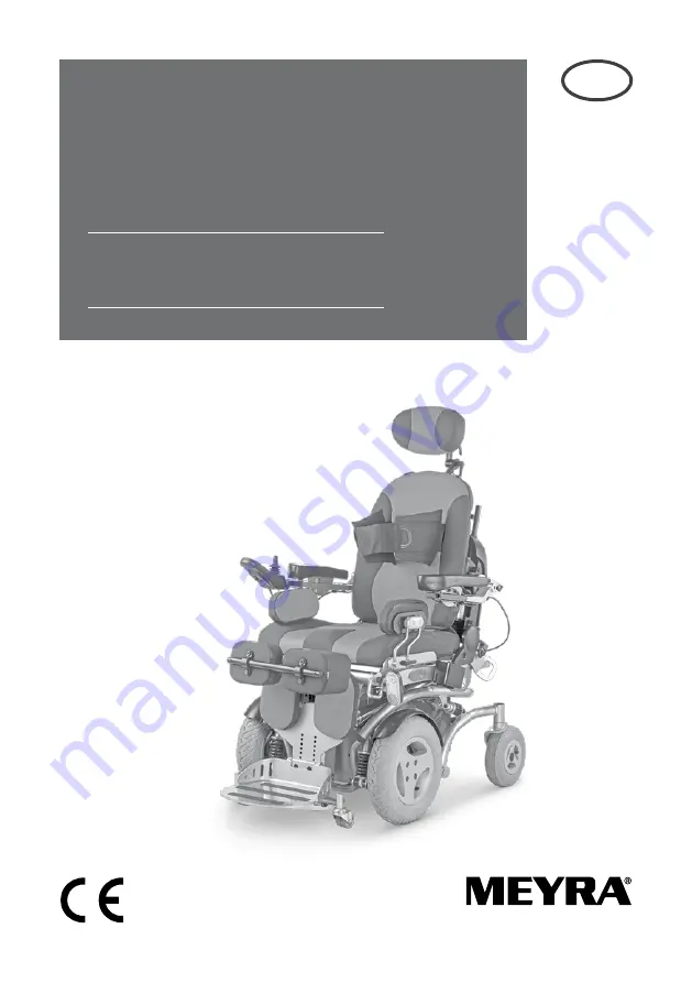
Operating manual
W e m o v e p e o p l e .
Electric wheelchair
Model 1.595 – 603 Vertical JuniorModel 1.595 – 604 Vertical Senior
Страница 1: ...en Operating manual W e m o v e p e o p l e Electric wheelchair Model 1 595 603 Vertical Junior Model 1 595 604 Vertical Senior...
Страница 2: ...kes 10 Service brake 10 Braking the wheelchair 10 Parking brake 10 Locking the brakes 11 Releasing the brakes 11 Drive push mode 12 Selecting the push mode 12 Selecting the motor mode 12 Selecting the...
Страница 3: ...pport 21 Knee cushions 22 Removing attaching the knee cushions 22 Side cushions 23 Adjusting the side cushions 23 Removing the side cushions 23 Removing attaching the side cushion pad 23 Torso support...
Страница 4: ...cing the fuses 36 Tyre damage on pneumatic tyres 36 Lighting 37 Adjusting the headlights 37 Fault correction 38 Technical data 39 Kilometric performance 39 Hill climbing ability 39 Data according to I...
Страница 5: ...vehicle Important information Attention Read and observe the following doc umentation belonging to the electric wheelchair before first use this operating manual the operating manual Operatingmod ule...
Страница 6: ...uest that you check the vehicle for possible transport dam age immediately on receipt prefera bly in the presence of the carrier The packaging of the wheelchair should be stored for a further transpor...
Страница 7: ...medical exams in order to ensure safety for active par ticipation in traffic Retrospective adjustments should be carried out solely by the specialist deal er LIFE SPAN We expect an average life span...
Страница 8: ...ing equipment 10 Selection lever drive push mode 11 Seat unit 12 Head support 13 Operating module 14 Driving wheel 15 Steering wheel Pos Description 1 Chest strap 2 Back support upholstery 3 Arm suppo...
Страница 9: ...from the basic position can be activated After selection of the menu by moving the joystick toward the front Adjustment into the basic position can be activated Locking down the adjustments If an adju...
Страница 10: ...ually disen gaged by switching the selection lever drive push mode on both drives to push mode HANDLING THE ELECTRIC WHEELCHAIR Securing the electric wheelchair The electric wheelchair is to be secure...
Страница 11: ...brakes To loosen the brakes swivel the selection lever drive push mode on both sides up as far as possible into push mode 2 Activation of the selection lever is in tended for an accompanying person At...
Страница 12: ...shunt the electric wheelchair Selecting the push mode 1 Switch off the operating module be cause the pushing will otherwise be made difficult by the electric system Therefore observe operation manual...
Страница 13: ...rder Note Charge the drive batteries via the oper ating module before the first journey 1 Selecting the motor mode Switch the drive motors to the drive mode 1 For this engage the brakes Observe chapte...
Страница 14: ...erating mod ule to the padded arm supports can be adjusted after loosening the clamping screw 3 Attention After the adjustment retighten the clamping screw Therefore also observe chapter Po sitioning...
Страница 15: ...heelchair on page 10 2 Insert the charger plug into the battery charging socket 1 of the operating module Attention Do not insert any objects other than the battery charger plug into the bat tery char...
Страница 16: ...wards slide the operating module into the desired position In doing so carefully guide the cable and retighten the clamping screw 1 securely Removing the operating module In order to remove the operat...
Страница 17: ...it possible for example to drive closer to a table remove the operating module more easily For regular drive mode the operating mod ule can be swivelled back toward the front until it engages back in...
Страница 18: ...Do not use the arm supports to lift or carry the wheelchair Angle of the arm supports The angle of the arm supports can be ad justed to the desires of the user Note During the electric adjustment of...
Страница 19: ...e Support the arm support slightly with one hand This makes it easier to use the locking button of the arm support The button 2 that locks the arm sup port must visibly lock into place again 3 Swivell...
Страница 20: ...levers 3 Removing and height adjusting the head support Loosen the clamping screw 4 to remove or adjust the head support Either remove the head support or slide it to the desired position Afterwards r...
Страница 21: ...perating manual Op erating module resp chapter Quick guide on page 9 within this docu ment For driving outdoors and in order to be able to overcome obstacles watch for sufficient ground clearance of t...
Страница 22: ...ght and depth by your specialist dealer Removing attaching the knee cushions In order to remove attach the knee cush ions pull up the locking lever 2 first Af terwards remove 3 or attach 4 the knee cu...
Страница 23: ...and position Afterwards retighten the clamping lever 2 Removing the side cushions After loosening the clamping lever 2 the respective side cushion can be removed or inserted Afterwards retighten the c...
Страница 24: ...E The splay wedge 2 can also be mounted retrospectively in a specialist workshop Removing attaching the splay wedge Loosen the clamping screw 4 for removal 3 and attachment 5 Retighten the clamping sc...
Страница 25: ...lination 1 can be adjusted through the operating module Special safety information for raising the seat seat height adjustment standing and lying functions Attention Only drive on slopes inclines and...
Страница 26: ...ight can now be increased up to 450 mm For adjustment view chapter Mode menu in the operating manual Op erating module resp chapter Quick guide on page 9 within this docu ment Raising the seat After r...
Страница 27: ...ly be carried out with the chest strap 2 applied and with correct ly adjusted knee cushions 3 Therefore observe the chapters Knee cushions on page 22 and Chest strap on page 29 For adjustment view cha...
Страница 28: ...on 1 may only be set with correctly adjusted knee cushions 2 and the chest strap applied 3 Therefore observe the chapters Knee cushions on page 22 and Chest strap on page 29 For adjustment view chapte...
Страница 29: ...prevents falling forward Fastening the chest strap Pull both straps forward and place close to the body To close the velcro fastener place both straps on top of each other and press Attention Make su...
Страница 30: ...the wheelchair and or user during transport in a motor ve hicle Fastening the shoulder strap Pull both belt halves to the front and slide the catch halves together so that they latch together Then ca...
Страница 31: ...be raised and low ered completely through the operating module Only this warrants a further use of the seat height adjustment Raising the seat To raise the seat press the lever 1 up first then activat...
Страница 32: ...hair on page 44 Observe the guideline Safety with Meyra wheelchairs also during transport inmotorvehicles This document and further information can be accessed on our website www meyra com in the Down...
Страница 33: ...andling instruc tions electric vehicles chapter Trans port in motor vehicles or with conveyors MAINTENANCE An incorrect or neglected cleaning and maintenance results in a limitation of the product lia...
Страница 34: ...ioning Carry out test yourself or with a helper Every 2 weeks depending on dis tance covered Check air pressure of the tyres Tyre filling pressure View Technical data on page 39 Carry out test yoursel...
Страница 35: ...ed consult a specialist workshop for repairs Every 6 months depending on fre quency of use Check Cleanness General condition View Service in document Safety and general handling instructions electric...
Страница 36: ...same type New fuses are available at gas stations or at specialist dealers Note If the safety fuse blows again take the battery to a specialist dealer for repair Fuse Mains battery fuse 1 The blade fu...
Страница 37: ...e Immediately have a defective LED lamp repaired by a specialist workshop Adjusting the headlights The headlights should be set in such a way that the light cone is visible on the road The lower edge...
Страница 38: ...to push mode Move the selection lever for the drive push mode into the drive mode posi tion on both sides Plug connection at one of the drives without contact Check the plug connec tions Malfunction i...
Страница 39: ...e duced by frequent uphill driving insufficient charging condition of the drive batteries low ambient temperature e g in win ter frequent acceleration and braking e g in city traffic aged sulphated dr...
Страница 40: ...edge without cushion 560 mm 1010 mm Seat angle 0 25 Back support angle 90 170 Back support belt height 580 mm 580 mm Foot support to seat lower shank length 290 mm 450 mm Static stability downhill 7 7...
Страница 41: ...edge without cushion 560 mm 1010 mm Seat angle 0 25 Back support angle 90 170 Back support belt height 580 mm 580 mm Foot support to seat lower shank length 380 mm 530 mm Static stability downhill 7 7...
Страница 42: ...t drive batteries 142 kg kg Empty weight without drive batteries head sup port knee cushions 180 kg kg Overall height without head support 1130 mm mm Overall length footplate up folded 950 mm mm Seat...
Страница 43: ...mm 230 70 12 pneumatic tyres max 2 5 bar Driving wheel 365 x 84 mm 3 00 8 pneumatic tyres max 2 5 bar Drive batteries 2 x 12 V 63 Ah 5 h 73 Ah 20 h sealed Max battery dimensions LxWxH 260 x 171 x 209...
Страница 44: ...at the arm supports or leg supports Removable parts are not suitable for carrying Drive mode Push mode Push only on level surfaces Indication for charging socket The product is not approved as a seat...
Страница 45: ...Year Calendar week Permitted user weight max permissible total weight Permitted axle weights Max permissible rising gradient Max permissible falling gradient Permitted maximum speed The product is app...
Страница 46: ...12 months Date Place date Signature Stamp of specialist dealer Next safety inspection in 12 months Date Place date Signature Serial no SN Delivery note no Model 46 Recommended safety inspection 1st ye...
Страница 47: ...nuts as well as worn out attachment holes due to frequent assembly work Furthermore damage to the drive and elec tronics caused by improper cleaning using steam cleaning equipment or the deliberate o...
Страница 48: ...48 NOTES...
Страница 49: ...49 NOTES...
Страница 50: ...50 NOTES...
Страница 51: ...e specialist dealer Serial no SN Delivery note no Model Stamp of specialist dealer Next safety inspection in 12 months Date Place date Signature 51 Warrantee Guarantee section Please fill out Copy if...
Страница 52: ...ing 2 D 32689 Kalletal Kalldorf Tel 49 5733 922 311 Fax 49 5733 922 9311 info meyra de www meyra de Your specialist dealer MEYRA 205 319 401 Status 2015 01 All technical modifications reserved Origina...