


3 Installation
page
8
ELC N6_N10-V3.1-09/11-GB subject to technical alterations
3.2 Connection
earthed lead network side
automatic cutout
earthed lead for the earthing
of lamp assembly
cable shield
lamp feeder cable
lamp assembly
L3
out1
L1 L2
L1
L2
L3
N
PE
out2
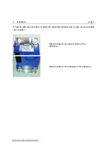
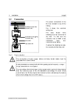
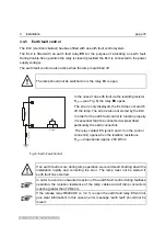
Fig. 3:
Power connection
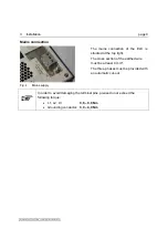
The power connections of the
ELC are situated on top of the
casing.
Fig. 3 shows the electrical
wiring plan.
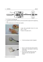
The lamp feeder cable
shielding must be connected to
the ELC. To this end the
connector has an EMC screw
connection (also see:
connection lamp cable).
If wished, the shielding can also
be connected to the lamp unit.
The connection of mains supply cables and lamp feeder cables must be
separated from control cables.
Quality standards according to EN 50160 regarding mains frequency, voltage
drops, transients etc. are required.
The one-phase short-circuit power at the supply point must be 20 times higher
than the nominal power of the UV-installation (accordingly the short circuit
current has to be 35 times higher than nominal current, alternatively the relative
short-circuit voltage has to be 2.8% lower).