


6
4.4 Service notes for the horizontal output stage
All supply voltages derived from the horizontal output
stage are protected by means of fuse-resistors which
disconnect the defective circuit section from the diode
split transformer in the case of a fault.
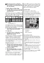
For faultfinding in the deflection circuit, the horizontal
output stage can be operated with a reduced supply
voltage by unsoldering the service strap
S1
and
moving it to the other position (dotted line in picture on
the right). The horizontal output stage now runs from
the D 25 voltage, which is about 15% of its normal
supply voltage.
This means that all pulse and supply voltages of the
horizontal output stage are about 15% of the values
shown in the circuit diagram. The waveforms do not
change. Since the vertical deflection is not running, the
vertical parabola is not superimposed on some of the
waveforms when they are measured with an oscillos-
cope. Incorrect waveforms and/or deviations from the
reduced (15%) values of the voltage indicate the possi-
ble cause of the fault.
4.5 Monitoring circuit
Faults in the high-voltage generator and CRT control
circuits are detected by a monitoring circuit. This circuit
consists primarily of the transistors Tr 1301 and Tr
1302. If this circuit is triggered, Tr 1302 cuts off and
initiates a power-off function via the control line
HPROT (this occurs if the HPROT pulses become grea-
ter than 4.5 V). The TV set then switches to standby
mode.
The following individual parameters are monitored:
a)
An increase in the high voltage
The positive amplitude of the g-pulse from the line
transformer is evaluated (this acts directly on input
HPROT of IC 3301, SDA 9380; Tr 1302 is not
affected).
b)
An increase in the beam current
In this case, the voltage at the terminal "B-ground"
of the diode split transformer becomes 0 Volt.
c)
Arcing or a short-circuit in a spark gap
In this case, the voltage at the terminal "B-ground"
of the diode split transformer becomes very positi-
ve. In cases a), b) and c), the TV set switches itself
off. After three unsuccessful attempts to restart, the
TV set switches permanently to standby mode and
the standby LED blinks five times.
d)
Voltage DS12
If the DS12 voltage drops below 9 V as the result of
a fault, Tr1303 cuts off, Tr1301 conducts and
TR1302 cuts off.
e)
H driver stage, H deflection
If the H deflection becomes unstable or operates
with an incorrect pulse-pause ratio, Tr1390 con-
ducts and Tr1302 cuts off.
For faultfinding in the horizontal and vertical deflec-
tion circuits, the monitoring circuit can be temporari-
ly disabled by connecting the pin HPROT (Pin 11 on
GKS 3) to ground. In this state, the screen is dark,
but the horizontal and vertical deflection circuits
receive the normal input signals.
☞
Switch on
the TV set
A300
330 V ?
Mains switch
D 1701
D 1703
D 1705
R 1704
Si 1703
R 1705
open-circuit?
Clocked
whistling noi-
se audible?
Short-circuit in C 1812
or
Short-circuit deflection
Connect oscilloscope
or voltmeter to C
1736
Short-circuit in
Tr 1710
no
no
no
yes
yes
no
yes
yes
Open-circuit in R 1701 or R 1702
Check Tr 1730 and D 1811 for
short-circuit
Voltage at C 1736 has
sawtooth waveform of
8...14 V (possibly slight
"bubbling" noise
audible?)
Short-circuit in D 1733 or C 1736
IC 1735 defective
Open-circuit in D 1733 or R 1735
Open-circuit in Tr 1710
No input signal to Tr 1710
LK 1740, Tr 1892, Tr 1870, IC
1895, or Tr 1891 defective
Open-circuit in R 1706 or R 1710


