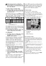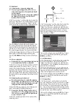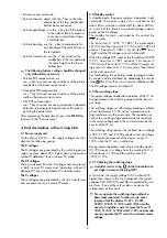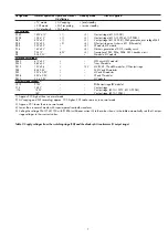
• Extreme corner correction
• Vertical linearity: adjust with the
- +
key so that the
amplitudes of the top, middle and
bottom boxes are equal.
• Vertical parallelogr.: use the
- +
key to tilt the picture
to the right or left to compensa-
te for any asymmetrical trape-
zoid distortion
• Vertical bending: use the
- +
key to compensate for
any bending of the vertical lines in
the test pattern.
• Vertical S-correction: use the
- +
key to adjust the
middle box in the test pattern to
the same height as the top or
bottom box
The following factory settings should be changed
only if absolutely necessary.
• Vertical EHT compensation: use
use
- +
key to cancel out any variations of the picture
amplitude as the beam current varies.
• Horizontal EHT compensation:
use
- +
key to cancel out any variations of the picture
width as the beam current varies.
• AFC EHT compensation:
use
- +
key to cancel out any asymmetrical trapezoid
distortion in particularly bright areas of the picture
by tilting the entire field.
After completing the adjustments, press the
MENU
key
to return to the "Service menu".
4. Brief descriptions with servicing hints
4.1 Power supply unit
On the chassis 601 G1..., the supply voltages are divi-
ded into the following groups:
The D voltages
The D voltages are generated by the switching power
supply and are about 20% higher during "operation
without H deflection" than in normal TV mode.
The DS voltages
These are derived from the D voltages and are present
in both normal TV mode and "operation without H
deflection". They are switched off in standby mode.
The C voltages
These voltages are generated by the line transformer
and are present only in normal TV mode.
4.2 Standby control
In standby mode, the power supply unit operates in pul-
sed mode. The power supply unit is switched on for
about 20 ms and then switched off for about 400 ms.
As a result of this, there is a sawtooth voltage superim-
posed on the D voltages.
The standby function is activated by the control line
STBY (L state).
The transistors Tr 1870, Tr 1880, the optocoupler
LK1740, and the transistors Tr 1730 and Tr 1890 all
conduct. Transistor Tr 1881 is cut off, the ON line is
"high" and the DS voltages are all switched off.
When the voltage D25 reaches the threshold of D1890
(12 V), transistor Tr 1891 conducts. This causes IC
1735 to cut off transistor Tr 1710 until the IC supply vol-
tage (pin 14) drops to 8 V. A new cycle is then started
via the start-up circuit.
For faultfinding, this pulsating mode (ecological stand-
by mode) can be disabled by
removing
the service
strap
S2
(the TV set then runs in service standby mode).
The DS voltages remain switched off.
4.3 The switching stage
The supply voltages needed for operation of the TV set
are generated in the switching stage and the line out-
put stage.
The switching stage is a self-starting blocking oscillator
whose transformer T 1705 acts as a protective isola-
ting transformer on the mains side. The regulation cir-
cuits of the switching stage compensate for variations
in the mains voltage and in the currents drawn by the
circuits of the TV set.
The switching stage receives the rectified mains voltage
A 300. R 1701 and R 1702 provide a start-up voltage
for the central component of the power supply, IC
1735, when the TV set is switched on.
During normal operation (and also in standby mode),
IC 1735 receives its voltage from the winding 16/14
of transformer T 1705 and the rectifier circuit D
1733/C 1736.
4.3.1 Checking the switching stage
Unsolder service strap
S1
(in the horizontal out-
put stage) or remove the plug GD1!
In this mode, the supply voltage D150 is about 50%
higher than shown in the circuit diagram. The supply
voltages D24, D25, D16 and D8 are protected by nor-
mal fuses. If one of these fuses blows, examine the
related parts of the circuit.
Never operate the switching stage without a
basic load connected. In other words, never
remove all of the diodes D 1811, D 1821,
D1831, D 1841, D 1851 and D 1861 simulta-
neously. In addition, never remove the fuses Si
1821, Si 1831, Si 1841 and Si 1851 and simulta-
neously operate the TV set with a reduced mains
voltage.
☞
☞
☞
5


