

Installation
Electric installation and device termination shall be
done by qualified persons only, by respecting the VDE
specifications and local regulations.
1. Power down the equipment.
2. Strip the wire by 7 mm, put on the end sleeve, insert to
terminal body and tighten the terminal screw with a screwdriver.
Wire cross section:
0.5 mm² - 4 mm² solid wire or
0.5 mm² - 2.5 mm² stranded wire with end sleeve
3. Device connection per wiring diagram.
Mounting
On standard DIN rail per DIN EN 50022 (35 x 7.5 mm), in junction
boxes and/or on distribution panels.
reset push button
3
2
1
5
4
Installation indications
G
Do not invert contacts L1 and LM (wrong current direction =>
device is permanently in the alarm mode)
G
Measuring current can be exceeded by max.
10 %, for higher motor current use a suitable current transfor-
mer.
G
If a current transformer is used, observe the
current direction (do not invert k and l!).
The
connection L1 on the secondary winding is
mandatory. The CPW is not able to measure without this con-
nection as current cannot flow towards L2 or L3. To measure
the cosj (phase shift difference between current and voltage)
voltage has to be applied at L1.
G
If the current falls below the measuring value
(1 A or 0.2 A) the CPW signals alarm.
G
If a frequency converter is used it is mandatory to install the
CPW behind the frequency converter. It is not possible to mea-
sure a reliable cos
ϕ
before the frequency converter.
Device Settings
G
turn the rotary time switch (3) to the left
G
turn the rotary cosj switch (5) to the right
G
install a bridge between S1 and S3 (error memory switched-off)
G
switch the motor on and let it run at its lowest speed => red
LED (2) is lighting
G
turn the rotary cosj switch (5) slowly to the left, until the relay
responds and the red LED turns off.
RPM-regulated motors (e.g. with frequency converter or delta-wye
connection) should run through all speeds to provide for reliable
operation. Check also functioning of bypass connections. Test
shut-down by error simulation (take off v-belt or check a pump
under dry running conditions).
When tests are finished install the bridges (error memory push-
button etc.), integrate the relay contacts into the malfunction
indication and set the required time.
Function settings by bridges S1, S2, S3
S1 - S2 open
relay released at underload
S1 - S2 bridged
relay activated at derating
S1 - S3 open
with error memory
S1 - S3 bridged
without error memory
With activated error memory (no bridge over S1-S3) the error
signal remains displayed until it is acknowledged or the operation
voltage is interrupted.
A NO contact at S1 - S3 allows a remote reset of the module.
7 mm
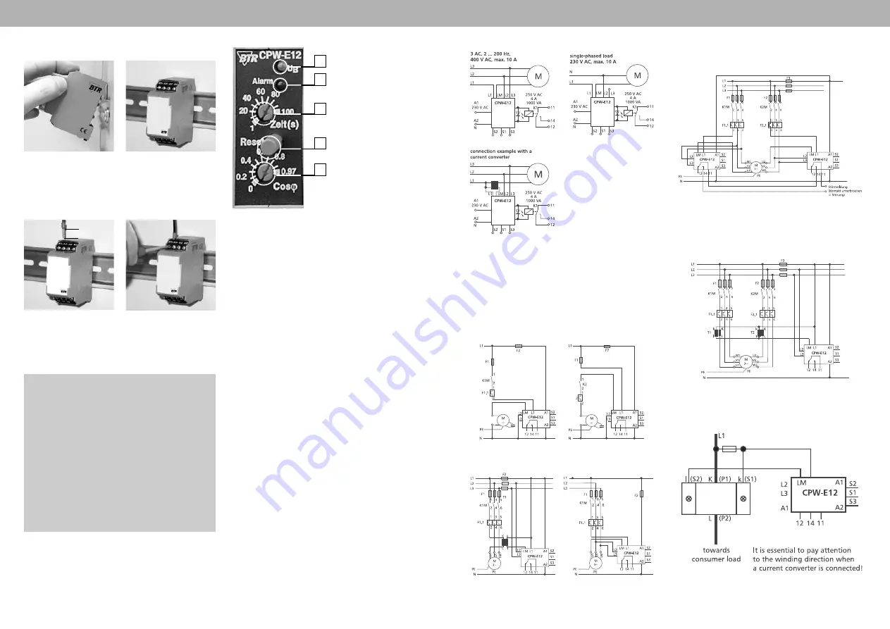
Display and Operation
green LED - operating voltage
indication
red LED - error indication
rotary switch for time setting
rotary switch for cos
ϕ
setting
Wiring Diagrams
Connection Examples
Important!
It is essential to consider the wiring diagram of the current con-
verter for the different connection examples!
Pay attention to the minimum current at the CPW-E12!
Connection to Single Phase Motors
Connection to Three Phase Motors
Connection Examples
Wiring Diagram for Current Converter
Connection to Two-stage Motors with
Separate Windings and Current Converter
Connection to Two-stage Motors with
Separate Windings


