


8
8 ACE 71 en
4.4
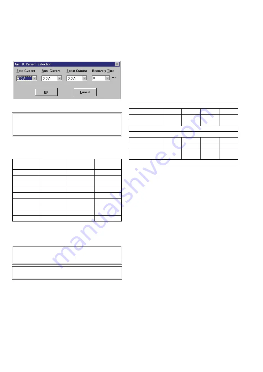
Limitation of the motor current
Current settings are preset in the factory in accordance with
the valve size. Settings can be modified in
Current Selection
window, Fig.11. In normal conditions there is no need to
modify these settings, but in case the customer changes
the actuator size and keep the same controller the settings
can be modified.
Use IPCOMM software for motor current setting.
Remember to push
Actual Parameters
button after current
value changes, otherwise changes will not be valid!
4.5
Option inputs and PLC commands
The Option inputs and PLC commands are preset in the fac-
tory. The settings can be modified to meet the process
requirements, for instance changing the time duration
speeds. Changes can be carried out in the
PLC-code
window,
Fig. 12 and Fig. 13. With the NelesAce delivery there is param-
eter list which includes program listing. The user may also
print the parameter list in start window by pressing the
printer button in the toolbar.
Factory settings and option input functions are indicated in
Table 2. When option inputs are in use, it's possible to
change the step size and time duration frequencies via DCS.
The customer can make the control logarithmic instead of a
linear control. The advantage of logarithmic control is that
controlling grade changes is much faster and more accu-
rate. Parameter changes can be done in following way:
Check the possible errors before modifying the PLC
commands.
Push
PLC>>
button to open
PLC-code
window.
Select parameter which you want to change.
To continue, follow instructions in Sections 4.5.1,
4.5.2 and 4.5.3.
The following is a description of the application of NelesAce
for the control system (DCS) vendor as the best available
method to control basis weight through use of the features
included in NelesAce.
The control method depends on the capabilities of the con-
trol system (DCS). In addition to the normal binary drive
open, drive closed output card a pulse train output card is
also needed to provide pulses to open and close the valve
in discrete steps.
In normal automatic mode the DCS uses pulses to control
NelesAce position. In this case DCS must have an appropri-
ate pulse output card which can send pulses at the correct
frequency (recommended time 25 ms per pulse). One pulse
from the control system (DCS) moves the NelesAce by one
pulse. Each pulse can equal 1/4 step, 1/2 step, 1 step, or 2
steps depending on which option or options are energized
and
how the NelesAce is programmed,
see table 2.
Normal movement is 1/2 step per pulse. Connection 7 (see
Fig. 3, Control 24 V DC) energized gives 1 step per pulse (=
option 1). Correspondingly connection 8 energized gives 2
steps per pulse (= option 2). Both connections 7 and 8 ener-
gized gives 1/4 step per pulse (= option 1&2).
When using 1/4 step mode the valve takes 28200 pulses for
full 0–100 % stroke, correspondingly 1/2 step takes 14100
pulses etc. Flow is controlled depending on the error
between actual and desired flow rate. The decision for step
size is made based on the magnitude of the error.
Fig. 12
Current selection window
NOTE:
Do not exceed the current setting of corresponding valve
size, Table 1.
Overload current may damage the valve shaft.
Table 1
Motor current limiting for different valve sizes
Valve
Stop current
(A
)
Run current
(A)
Boost current
(A)
DN 50-65
0.8
1.2
1.2
DN 80-100
1.2
1.5
1.5
DN 150
2.0
3.8
3.8
DN 200
2.0
3.8
3.8
DN 250
2.4
4.6
4.6
DN 300
2.8
5.1
5.1
DN 350
2.8
5.1
5.1
DN 400
2.8
5.1
5.1
DN 500
2.8
5.1
5.1
NOTE:
If error condition is on, while PLC commands are modified
all PLC parameters will be erased!
NOTE:
Don’t change ramp parameters!
Table 2
Factory settings and option inputs
Pulse duration
Option input 1
0 V DC
24 V DC
0 V DC
24 V DC
Option input 2
0 V DC
0 V DC
24 V DC
24 V DC
Step size
1/2 step
1/1 step
2/1 step
1/4 step
max. step input frequency 400 Hz except 2/1-step 200 Hz
Time duration
Option input 1
0 V DC
24 V DC
0 V DC
24 V DC
Option input 2
0 V DC
0 V DC
24 V DC
24 V DC
Time duration
speed
150 Hz
300 Hz
600 Hz
1200 Hz
min. time duration frequency is 50 Hz and max. 2 kHz


