


8 ACE 71 en
3
1
GENERAL
1.1
General view
Metso NelesAce
®
basis weight control system comprises a V-
port segment valve, an actuator and a control unit.
The valve is a standard R-series V-port segment valve.
A stepping motor is used in the actuator to reach the best
possible degree of regulation. The actuator is equipped
with both open and close position limit switches and with a
position transmitter.
The process control system transmits a digital signal to the
control unit which in turn automatically controls the actua-
tor. Manual operation is also possible.
1.2
Operating principle of the control unit
The step motor controller is in command of the four-wire
connected step motor in the valve actuator. The controller's
protection class is IP65. Input signals are transmitted to the
controller through six digital input channels. Alternatives
are pulse duration interface or time duration interface.
There are also optional input channels (Option 1 and
Option 2). When option inputs are in use, it is possible to
change the step size and time duration frequencies
remotely. The process control system (DCS) transmits a
pulse mode. The pulse mode then drives the step motor to
either the open or close directions depending on the chan-
nel which DCS is using (open or close). The movement
stops if the pulses end or the actuator reaches the limit
switch. In time duration mode the step motor starts to
move from the pulse leading edge and stops from the pulse
trailing edge or when the actuator reaches the limit switch.
The opening angle of the actuator is 0 to 90º. The default
factory value for the step setting is 1/2 step per pulse where
14100 pulses equals to 90 degree movement. The accuracy
of regulation can be changed. In this case the step setting
must be changed by programming it to 1/1 step (7050
pulses). The control unit is also equipped with inputs for
two limit switch signals and feedback potentiometer signal.
RS232/485 interface compatible IPCOMM software is deliv-
ered with the control unit. This software allows parameter
changes to the control unit.
1.3
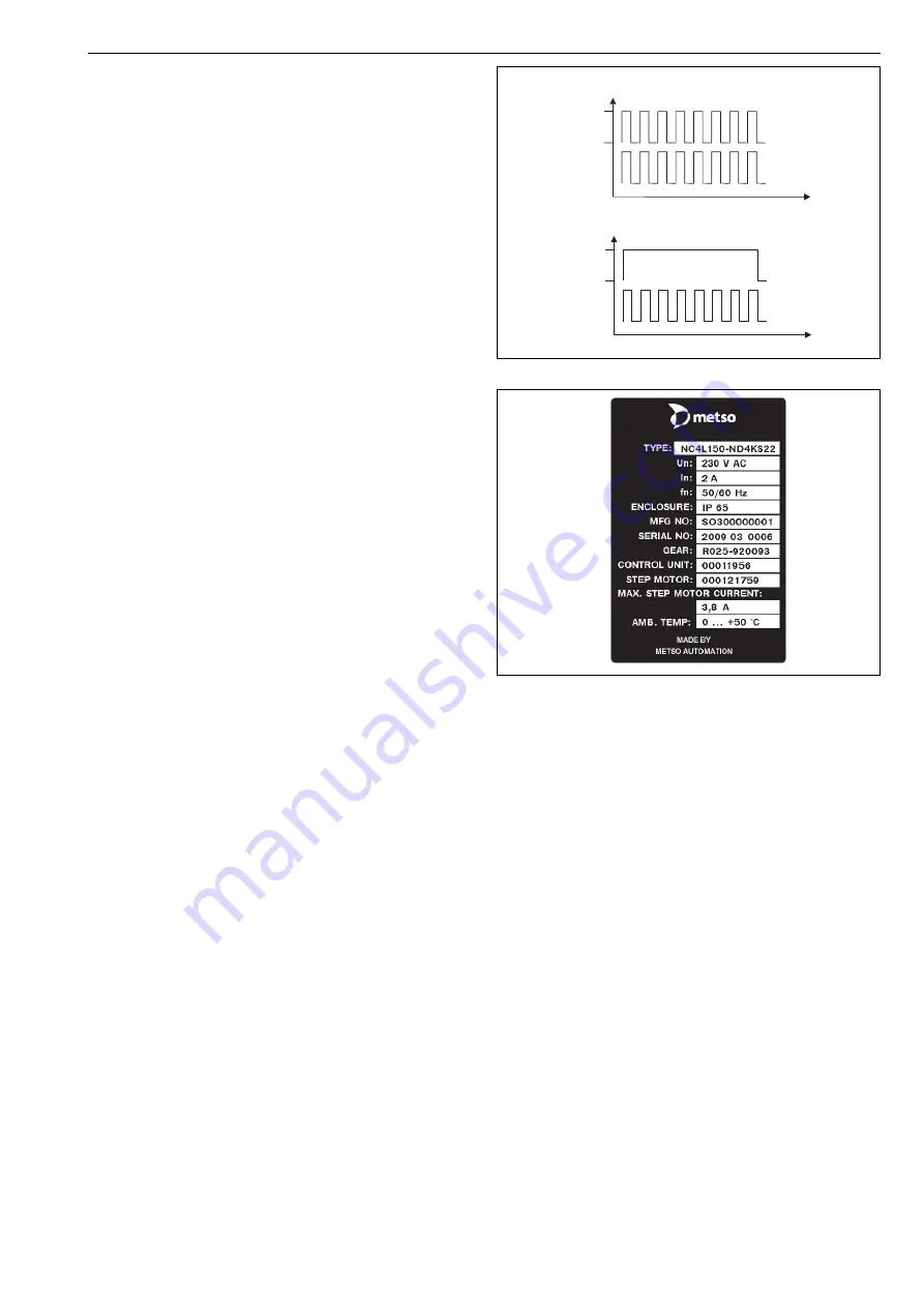
Markings
The valve controller is equipped with an identification plate
sticker, see Fig. 2. Identification plate markings from top to
bottom are:
Type code of the actuator and control unit
Nominal voltage
Nominal current
Supply voltage frequency
Protection class
Manufacturer number
Serial number
Gear ID
Control unit ID
Step motor ID
Max. step motor current
Ambient temperature
1.4
Technical specifications
1.4.1
Valve
See Installation, Maintenance and Operating instructions 3
R 74 for valve installation instructions.
Recommendation: Installation of the valve: 7 x DN down-
stream side and 10 x DN upstream side distance of the pip-
ing curve. Installing the valve into pipeline. See figure 3.
1.4.2
Actuator
Stepping motor:
Motor type
ZSH87/3.200.5
Number of steps
200
Step angle
1.8° in full step mode
Compatible with ministep-mode
Protection class
IP68
Insulation class
F
EMC and CE approved (EN 60034-1)
Gear:
Gear ratio
1:141
Limit switches:
Contacts
normally closed (NC)
Position transmitter:
Output signal
4–20 mA
External load
1 k
Ω
Fig. 1
Pulse and time duration modes
Fig. 2
Example of the identification label
0 V
24 VDC/10,5mA
t
t
0 V
24 VDC/10,5mA
Pulse duration mode
Time duration mode
input pulse
pulse to stepping motor
input pulse
pulse to stepping motor


