SECTION 3 - M. FRAME, ADJ. RING, TRAMP REL. & CLRNG JACK ASSY
3-12
MP SERIES CONE CRUSHER TECHNICAL REFERENCE MANUAL
MP800
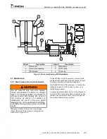
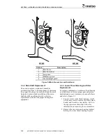
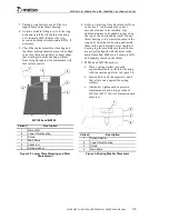
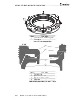
1. Starting at any release cylinder, identify, on
the outside surface of the adjustment ring
flange, four spots 90° apart by stamping or
painting the numbers 1, 2, 3 and 4.
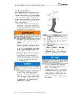
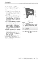
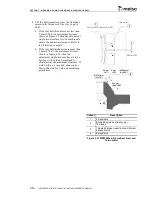
2. Measure the distance from the top of the
adjustment ring flange to the bottom surface
of the upper main frame flange at the four
numbered spots as shown in Figure 3-10.
Record these measurements.
3. At periodic intervals remeasure these points
and compare them to the original
dimensions. Comparing the two sets of
dimensions will show at a glance how much
wear has taken place and if the wear is even
all the way around the Crusher. Due to
casting and machining variations this is the
only accurate method in which wear can be
determined.
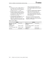
4. When any one of the four check dimensions
measures less than the initial recorded
dimensions by the amount shown in
Table 3-1 the seat liner and fulcrum bars
need replacing. This much vertical wear
means that only 5 mm (0.19") of material is
left on the seat liner.
The 8 mm (0.32") difference between the two
measurements indicates the seating surface has
worn and, according to the table, the seat liner and
fulcrum bars need replacing.
Table 3-1 Seat Liner Wear
MP800
MP1000
Maximum Vertical Wear
8 mm (0.32")
Maximum vertical wear
10 mm (0.38")
Example:
Example:
Original recorded
measurement
350 mm (13.78")
Periodic dimensional check
50 mm (2.00")
Periodic dimensional check 342 mm (13.46")
Original recorded
measurement
40 mm (1.62")
Difference
8 mm (0.32")
Difference
10 mm (0.38")
Содержание MP1000
Страница 1: ...Nordberg MP Series Cone Crusher ...
Страница 2: ......
Страница 4: ......
Страница 6: ......
Страница 8: ......
Страница 64: ...SECTION 0 SAFETY 0 56 MP SERIES CONE CRUSHER TECHNICAL REFERENCE MANUAL ...
Страница 66: ......
Страница 74: ......
Страница 154: ...Countershaft and Countershaft Box Callout Description 1 Countershaft 2 Countershaft box 1 2 ...

