SECTION 3 - M. FRAME, ADJ. RING, TRAMP REL. & CLRNG JACK ASSY
MP SERIES CONE CRUSHER TECHNICAL REFERENCE MANUAL
3-7
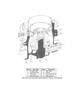
3.3.5 Main Frame Pins and Pin Bushings
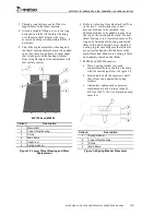
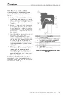
The main frame pins prevent the adjustment ring
from rotating in respect to the main frame and also
guide the adjustment ring back to its original
position when the ring lifts due to tramp iron or
packed material in the crushing cavity (refer to
Figure 3-6). Repeated adjustment ring lift is not
normal, is not an acceptable method of operation,
and can usually be corrected by proper feeding and
correct crusher settings.
Incorrect operation with excessive ring movement
will result in wear of main frame pins and worn pin
bushings. See below for proper procedure for
checking for bushing wear. Any wear on the main
frame pin bushing is easily checked once the pin
covers are removed. Due to the rotation of the head
in relationship to the bowl, the adjustment ring will
want to rotate in the opposite direction as the head
rotation. Since this force will be acting on the
adjustment ring in one direction only, the main
frame pins and the pin bushing in the adjustment
ring will have a tendency to wear on one side only.
Excessive pin or bushing wear will result in a
concentration of wear on the release cylinder rods
in the area where the rods pass through the main
frame. The main frame pins and the pin bushings
should be replaced when they show signs of
excessive wear. Since excessive pin wear is
unusual, the main frame pins will rarely require
replacement.
Replace pin bushing as follows:
1. Lock out and tag all electrical power
supplied to the power unit and Crusher and
depressurize the clamping and tramp release
circuits by opening the clamping cylinder
and tramp release cylinder needle valves
located on the side of the hydraulic power
unit at the hose connection area.
2. Remove the pin covers to inspect the pin
bushings for wear. If the pin bushings show
excessive wear continue with the
replacement procedure.
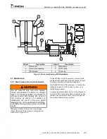
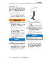
3. Slightly lift the adjustment ring off the
frame and rotate the ring to center the main
frame pins in the bushings. Refer to
Figure 3-7 for correct lifting of adjustment
ring.
4. Once the pin is centered, remove the
bushing by prying the bushings out.
NOTICE
Allowing the adjustment ring to bounce will
void the warranty.
WARNING
Prior to performing maintenance work on
any part of the Crusher, lockout and tag all
electrical power supplied to the power unit
and Crusher and release stored pressure in
all hydraulic circuits. Death or serious injury
may result if the Crusher systems are
activated while personnel are in, on or near
the Crusher. Turn the POWER OFF/ON
switch located on the local control station to
the OFF position and lock out and tag the
power supply to the power unit and Crusher.
Depressurize the hydraulic circuits by
opening (turn counter-clockwise) the needle
valves located at the hydraulic power unit
cabinet. This will vent the pressurized oil in
the circuits back to tank but it will not release
the nitrogen pre-charge pressure in the
clamping circuit accumulator found inside
the power unit or the tramp release circuit
accumulators shared by the tramp release
cylinders. Do not perform maintenance on
any accumulator until the hydraulic circuits
have been depressurized and the nitrogen
pre-charge pressure is safely released.
Содержание MP1000
Страница 1: ...Nordberg MP Series Cone Crusher ...
Страница 2: ......
Страница 4: ......
Страница 6: ......
Страница 8: ......
Страница 64: ...SECTION 0 SAFETY 0 56 MP SERIES CONE CRUSHER TECHNICAL REFERENCE MANUAL ...
Страница 66: ......
Страница 74: ......
Страница 154: ...Countershaft and Countershaft Box Callout Description 1 Countershaft 2 Countershaft box 1 2 ...


