


Doc#
M9005 • REV N
(May 2017) Page
5 of 12
Alarm Limit Triac Output Wiring
The triac output(s) are electro-optically isolated from each other, power, and the internal
circuit. These are medium-power devices with high immunity to electrical transients. If
desired, each triac can be supplied from an AC voltage source different from the main sup
-
ply. The triacs can be connected in series with the triacs of other units. See Figure 4. Parallel
connection of two switches doubles the triac holding (minimum load) current requirements.
The maximum triac supply voltage is 250 VAC. The worst case triac leakage (off) current is 2
mA. The maximum triac holding current is 35 mA at 25°C (60mA at -40°C) which requires that
the relay pull-in current have a greater value. Do not use a DC supply. The triacs can be set for
N.C. or N.O. operation by positioning the Limit 1 / Limit 2 switches accordingly.
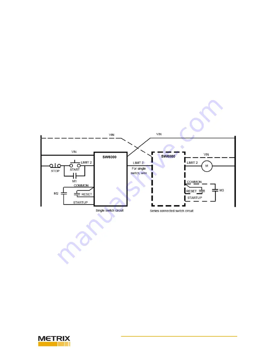
Typical Control Circuits SW6000 w/AC Power Wired to Interrupt Motor Starter
(series connection)
a. Set each SW6000 for N.C. (normally closed) operation. (See Figure 2)
b. M2, M3 and remote reset contacts must each be isolated.
Figure 4: Parallel connection of two SW6000
a. Set each SW6000 for N.C. (normally closed) operation. (See Figure 2)
b. M2, M3 and remote reset contacts must each be isolated.
Alarm Limit FET Output Wiring (optional)
The optional FET limit output(s) provide a low leakage switch for DC inputs to PLC’s or other
devices. Do not use on an AC supply. Observe proper polarity when wiring the FET(s) (See
figure 2). Damage to the FET(s) will result from improper wiring. As with the triacs, the FET(s)
can be set for N.C. or N.O. operation by positioning the Limit 1/Limit 2 switches accordingly.
Limit Trip Delay
The base unit has an adjustable (1-15 sec.) limit trip delay. The vibration level must be con
-
tinuously above the limit setting for the duration of the time delay before the output devices
switch. The 4-20 mA output is not affected by this time delay. To reset the limit output
devices, the internal reset push-button or the optional external reset push-button must be
pressed. Remote reset by a N.O. push-button or momentary contacts may be made by wiring
to the remote reset terminals. Note that the vibration level must be below the trip level for
the reset to function.


