MX 20
37
3.4.3 - AC VOLTAGE MEASUREMENT
3.4.3 - AC VOLTAGE MEASUREMENT
3.4.3 - AC VOLTAGE MEASUREMENT
3.4.3 - AC VOLTAGE MEASUREMENT
3.4.3 - AC VOLTAGE MEASUREMENT
· Connect the black lead to the terminal marked COM and the red
lead to the terminal marked VW .
· Set the rotary switch to the AC volts position.
· Apply the test prods to the points across which the voltage is to
be measured and read the result directly from the display. The
display also shows the unit of measurement (mV or V).
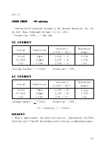
· Accuracy, resolution, and input resistance: see detail specifica-
tions.
CAUTION
Under no circumstances should a voltage excee-
ding 1000V
D C
or 750V
A C
be applied to the instru-
ment, and, where pulse signals are present (for
example in the line scanning circuits of television
sets), use a type HA0902 filter probe.
· In manual ranging mode, if the display shows «1 » the range
selected is too low. Switch to the next higher range by pressing the
MAN RANGE/AUTO RANGE key (press once for less than 2
seconds.)
3.4.4 RESISTANCE MEASUREMENT AND DIODE CHECKS
3.4.4 RESISTANCE MEASUREMENT AND DIODE CHECKS
3.4.4 RESISTANCE MEASUREMENT AND DIODE CHECKS
3.4.4 RESISTANCE MEASUREMENT AND DIODE CHECKS
3.4.4 RESISTANCE MEASUREMENT AND DIODE CHECKS
·Measuring resistance, like measuring voltage, can be carried out
in autoranging or manual modes (see use of the MAN RANGE/
AUTO RANGE key).
· Connect the black lead to the terminal marked COM and the red
lead to the terminal marked VW on the multimeter and set the rotary
switch to W
.


