background image

11

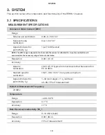
TEROS 12

Output

DDI serial or SDI-12 communications protocol

Data Logger Compatibility

Any data acquisition system capable of 4.0- to 15-VDC power  
and serial or SDI-12 communication

PHYSICAL SPECIFICATIONS

Dimensions

Length

9.4 cm (3.70 in)

Width

2.4 cm (0.95 in)

Height

7.5 cm (2.95 in)

Needle Length

5.5 cm (2.17 in)

Cable Length

5 m (standard) 
75 m (maximum custom cable length)

NOTE:  Contact 

Customer Support

 if a nonstandard cable length is needed.

Connector Types

3.5-mm stereo plug connector or stripped and tinned wires

ELECTRICAL AND TIMING CHARACTERISTICS

Supply Voltage (VCC to GND)

Minimum

4.0 VDC

Typical

NA

Maximum

15.0 VDC

Digital Input Voltage (logic high)

Minimum

2.8 V

Typical

3.6 V

Maximum

3.9 V

Содержание TEROS 12

Страница 1: ...TEROS 12 ...

Страница 2: ...cifications 10 3 2 Components 13 3 3 Theory 14 3 3 1 Volumetric Water Content 14 3 3 2 Temperature 15 3 3 3 Electrical Conductivity 15 3 3 4 Converting Bulk EC to Pore EC 15 3 3 5 Pore Water Versus Saturation Extract EC 16 4 Service 18 4 1 Calibrations 18 4 1 1 Mineral Soils 18 4 1 2 Soilless Media 18 4 1 3 Apparent Dielectric Permittivity 19 4 2 Cleaning 19 4 3 Troubleshooting 19 18225 01 4 26 20...

Страница 3: ...ii TEROS 12 4 4 Customer Support 20 4 5 Terms and Conditions 21 References 22 Index 23 ...

Страница 4: ...iii ...

Страница 5: ...l guides the customer through the sensor features and describes how to use the sensor successfully TEROS 12 APPLICATIONS Volumetric water content VWC measurement Soil substrate water balance Irrigation management Soil EC measurement Soil substrate temperature measurement Solute fertilizer movement Prior to use verify the TEROS 12 arrived in good condition METER recommends testing the sensors with ...

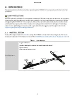
Страница 6: ...e the proper protections in place to safeguard sensors from damage If installing sensors in a lightning prone area with a grounded data logger see the application note Lightning surge and grounding practices 2 1 INSTALLATION Follow the steps listed in Table 1 to set up the TEROS 12 and start collecting data For more detailed installation information consult the TEROS Sensors Best Practices Install...

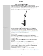
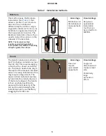
Страница 7: ...te Hole Avoid interferring objects If the TEROS 12 is installed near large metal objects they can affect the sensor function and distort readings Avoid large objects like roots or rocks that could potentially bend the needles Auger or trench a hole to the desired sensor installation depth and direction according to the installation method desired Insert Sensor ATTENTION Minimize air gaps around th...

Страница 8: ... side will provide measurements at a more discreet depth See Measurement volume of METER volumetric water content sensors for more information on sensor measurement volume Backfill the Hole Return soil to the hole packing the soil back to its native bulk density Do not hit the ferrite core as this could potentially pull the sensor out of the soil Connect to Logger Connect the 3 5 mm stereo plug co...

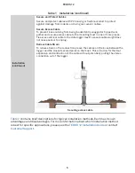
Страница 9: ...le weight does not cause sensor to unplug Relieve Cable Strain To relieve strain on the connections leave the cables a little loose between the logger and the closest secured point on the mast This will allow for thermal expansion and contraction of the cable without potentially pulling the stereo connection out of the logger ERROR OK TEST P1 P2 P3 P4 P5 P6 Securing excess cable Table 2 contains b...

Страница 10: ...ent site Disadvantage Requires a specialized installation tool that can be rented from METER Trench The trench installation method is best for shallow installations less than 40 cm This requires digging a trench with a shovel excavator etc The trench needs to be dug to the depth of the deepest installed sensor For deep installations this may require a large trench The sensor is then installed care...

Страница 11: ...tandard with a 5 m cable It may be purchased with custom cable lengths for an additional fee on a per meter basis This option eliminates the need for splicing the cable a possible failure point However the maximum recommended length is 75 m 2 2 1 CONNECT TO METER DATA LOGGER The TEROS 12 sensor works seamlessly with METER ZENTRA EM60 or Em50 data loggers Logger configuration may be done using eith...

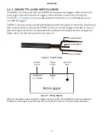
Страница 12: ...with screw terminals Connect the TEROS 12 wires to the data logger illustrated in Figure 2 with the supply wire brown connected to the excitation the digital out wire orange to a digital input and the bare ground wire to ground Ground bare Data orange Power brown Figure 2 Pigtail wiring Switched 4 15 VDC Digital In Data Logger G Data orange Ground bare Power brown Figure 3 Wiring diagram NOTE The ...

Страница 13: ...tion 2 Obtain an adapter cable from METER The adapter cable has a connector for the stereo plug connector sensor jack on one end and three wires or pigtail adapter on the other end for connection to a data logger The stripped and tinned adapter cable wires have the same termination as seen in Figure 3 the brown wire is excitation the orange is output and the bare wire is ground NOTE Secure the 3 5...

Страница 14: ... is calibrated to A custom calibration will accommodate the necessary ranges for most substrates Resolution 0 001 m3 m3 Accuracy Generic calibration 0 03 m3 m3 typical in mineral soils that have solution EC 8 dS m Medium specific calibration 0 01 0 02 m3 m3 in any porous medium Apparent dielectric permittivity εa 1 40 soil range 1 εa unitless 40 80 15 of measurement Dielectric Measurement Frequenc...

Страница 15: ... 4 cm 0 95 in Height 7 5 cm 2 95 in Needle Length 5 5 cm 2 17 in Cable Length 5 m standard 75 m maximum custom cable length NOTE Contact Customer Support if a nonstandard cable length is needed Connector Types 3 5 mm stereo plug connector or stripped and tinned wires ELECTRICAL AND TIMING CHARACTERISTICS Supply Voltage VCC to GND Minimum 4 0 VDC Typical NA Maximum 15 0 VDC Digital Input Voltage lo...

Страница 16: ...A Typical 3 6 mA Maximum 16 0 mA Current Drain while asleep Minimum NA Typical 0 03 mA Maximum NA Operating Temperature Range Minimum 40 C Typical NA Maximum 60 C NOTE Sensors may be used at higher temperatures under certain conditions contact Customer Support for assistance Power Up Time DDI serial Minimum 80 ms Typical NA Maximum 100 ms Power Up Time SDI 12 Minimum NA Typical 245 ms Maximum NA ...

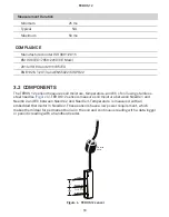
Страница 17: ...C of soil using stainless steel needles Figure 4 TEROS 12 sensors measure soil moisture between Needle 1 and Needle 2 and EC between Needle 2 and Needle 3 Temperature is measured with an embedded thermistor in Needle 2 These sensors have a low power requirement which makes them ideal for permanent burial in the soil and continuous reading with a data logger or periodic reading with a handheld read...

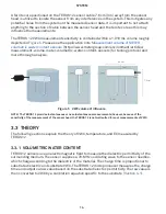
Страница 18: ...3 cm 3 cm 3 cm 1 cm 1 cm 7 5 cm 9 3 cm 3 cm Figure 5 VWC volume of influence NOTE The TEROS 12 provides instantaneous or near instantaneous measurements however because of the sensitivity of the measurement of the sensor head the TEROS 12 is not well suited for spot measurements of VWC 3 3 THEORY The following sections explain the theory of VWC temperature and EC measured by TEROS 12 3 3 1 VOLUMET...

Страница 19: ...k EC measurement is factory calibrated to be accurate within 3 of measurement from 0 to 20 dS m This range is adequate for most soil and growth substrate applications EC measurements above 10 dS m are sensitive to contamination of the electrodes by skin oils etc Be sure to read Section 4 2 about sensor cleaning if measuring the EC of salty soils 3 3 4 CONVERTING BULK EC TO PORE EC For many applica...

Страница 20: ...s a simple and easy method for determining b 0 for individual soil types which improves the accuracy of the calculation of p in most cases METER testing indicates that the method for calculating p Equation 1 results in good accuracy 20 in moist soils and other growth media In dry soils where VWC is less than about 0 10 m3 m3 the denominator of Equation 1 becomes very small leading to large potenti...

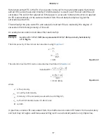
Страница 21: ... example calculation illustrates this relationship Example A soil is at 0 1 m3 m3 VWC has a pore water EC of 0 7 dS m and a dry bulk density of 1 5 Mg m3 The total porosity of the soil can be calculated using Equation 3 Equation 3 φ ρb ρs 1 1 5 2 65 0 43 The saturation extract EC can be calculated as illustrated in Equation 4 Equation 4 SolutionEC σp Θ σp φ Θ φ 0 7 0 7 0 0 43 0 162 dS m where is t...

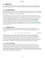
Страница 22: ...ibration or contact Customer Support 4 1 1 MINERAL SOILS According to METER tests a single calibration equation will generally suffice for most mineral soil types with ECs from 0 dS m to 8 dS m saturation extract VWC is given by Equation 5 Equation 5 Θ m3 m3 3 879 10 4 RAW 0 6956 A linear equation is used for the mineral soil calibration because it provides the best predictions of VWC in the range...

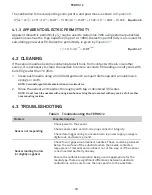
Страница 23: ... cloth NOTE Avoid detergents that contain lotions or moisturizers 2 Rinse the sensor and needles thoroughly with tap or deionized DI water NOTE Do not touch the needles with an ungloved hand or bring them in contact with any source of oil or other nonconducting residue 4 3 TROUBLESHOOTING Table 3 Troubleshooting the TEROS 12 Problem Possible Solution Sensor not responding Check power to the sensor...

Страница 24: ...ration may need to be performed Soils with a bulk EC greater than 10 dS m require substrate specific calibrations Section 4 1 Cable or stereo plug connector failure If a stereo plug connector is damaged or needs to be replaced contact Customer Support for a replacement connector and splice kit If a cable is damaged follow these guidelines for wire splicing and sealing techniques 4 4 CUSTOMER SUPPO...

Страница 25: ...MS AND CONDITIONS By using METER instruments and documentation you agree to abide by the METER Group Inc USA Terms and Conditions Please refer to www metergroup com company meter group inc usa terms conditions for details ...

Страница 26: ...e water conductivity sensor Soil Science Society of America Journal 64 6 1922 1925 Topp GC David JL and Annan AP 1980 Electromagnetic determination of soil water content Measurement in coaxial transmission lines Water Resources Research 16 3 574 582 ...

Страница 27: ...ity 15 pore water electrical conductivity 15 16 saturation extract electrical conductivity 16 17 F ferrite core about 14 installation 3 I installation ferrite core 3 installation tool 2 methods 6 7 borehole 6 trench 6 orientation 4 preparation 3 tools needed 2 M maintenance See cleaning the sensors R references 22 S safety 2 soil moisture 13 specifications 10 13 data logger compatibility 11 dielec...

Страница 28: ...itions 21 22 theory 14 17 electrical conductivity 15 17 See also electrical conductivity temperature 15 volumetric water content 14 VWC See theory volumetric water content troubleshooting 19 20 V volumetric water content specifications 10 theory 14 ...

Страница 29: ...4 26 2018 METER Group Inc USA 2365 NE Hopkins Court Pullman WA 99163 T 1 509 332 5600 F 1 509 332 5158 E info metergroup com W www metergroup com 2018 All Rights Reserved Printed in USA ...

Страница 30: ......

Отзывы: