


Troubleshooting
65
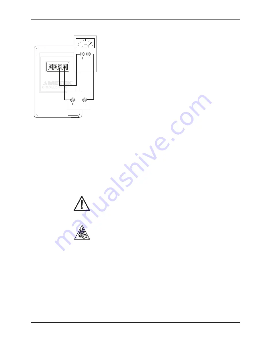
1. Remove coaxial cable from the transmitter
terminals.
2. Without changing any data stored in the
transmitter, connect a Drexelbrook capacitance
substitution box (401-6-8) or an NPO test capacitor
from the probe terminal to the GND terminal on
the transmitter. (Select a capacitance value that
produces between 4 and 20 mA of loop current.)
3. Observe the loop current over a 12-hour period to
confirm the stability of the unit. If the readings
remain stable for this period, then the problem
is not in the transmitter. If the loop current has
changed more than 1% during the test period, then
the unit is defective. Please contact the Service
department for further instructions regarding
repair or replacement.
6.7 Troubleshooting Sensing Element
Troubleshooting sensing element requires use of
an analog ohmmeter
. Digital meters do not properly
measure resistance for the purpose of this test. An
analog ohmmeter typically provides more current when
measuring resistance, which is required to detect a
pinhole or crack in the sensing element insulation. In
addition, digital meters frequently give erroneous results
due to a battery-like effect when dissimilar metals contact
conductive liquids.
CAUTION: Sensing element is intrinsically
safe. Therefore, when using this product, it is
recommended that all service activity comply with
appropriate guidelines.
Remove sensing element from vessel to a safe area.
Test outlined in steps 1 and 2 can be performed
in a metal test vessel filled with high conductivity
water. Depending on locality, tap water may not be
suitable. If not, a spoonful of table salt may work.
In the following tests, if it is not possible to raise or lower
level in vessel, sensing element may be suspended in a
metal pipe or other container that is filled with conductive
water (see above note) and connected to grounded sensing
element condulet. If container is not metallic, then a
ground wire or rod is needed to be placed into the water
and referenced to sensing element condulet or mounting
devices.
6.6.1 Transmitter Drift Test (Continued)
GND
V -
V +
M -
SERIAL NO.
MODEL NO.
YEAR OF MANUFACTURE
24 VDC
Transmitter
mA Meter
on Record
Figure 6-4
Содержание RCT 10 series
Страница 4: ......
Страница 8: ...SECTION 1...
Страница 26: ...SECTION 3...
Страница 46: ...SECTION 4...
Страница 57: ...Configuration Calibration 49 5 4 Set Up Procedures...
Страница 58: ...RCT 10 11 12 13 Series 50 5 4 Set Up Procedures Continued...
Страница 59: ...Configuration Calibration 51 5 4 Set Up Procedures Continued...
Страница 66: ...SECTION 6...
Страница 80: ...SECTION 7...
Страница 86: ...APPENDIX A...
Страница 87: ...Appendix A A 1 APPENDIX A APPROVAL DRAWINGS A 1 ATEX APPROVAL DRAWINGS...
Страница 88: ...RCT 10 11 12 13 Series A 2 A 1 ATEX APPROVAL DRAWINGS Continued...
Страница 89: ...Appendix A A 3 A 1 ATEX APPROVAL DRAWINGS Continued...
Страница 90: ...RCT 10 11 12 13 Series A 4 A 1 ATEX APPROVAL DRAWINGS Continued...
Страница 91: ...Appendix A A 5 A 1 ATEX APPROVAL DRAWINGS Continued...
Страница 92: ...RCT 10 11 12 13 Series A 6 A 1 ATEX APPROVAL DRAWINGS Continued...
Страница 93: ...Appendix A A 7 A 1 ATEX APPROVAL DRAWINGS Continued...
Страница 94: ...RCT 10 11 12 13 Series A 8 A 1 ATEX APPROVAL DRAWINGS Continued...
Страница 95: ...Appendix A A 9 A 1 ATEX APPROVAL DRAWINGS Continued...
Страница 96: ...RCT 10 11 12 13 Series A 10 A 1 ATEX APPROVAL DRAWINGS Continued...
Страница 97: ...Appendix A A 11 A 1 ATEX APPROVAL DRAWINGS Continued...
Страница 98: ...RCT 10 11 12 13 Series A 12 A 2 CSA APPROVAL DRAWINGS...
Страница 99: ...Appendix A A 13 A 2 CSA APPROVAL DRAWINGS Continued...
Страница 100: ...RCT 10 11 12 13 Series A 14 A 2 CSA APPROVAL DRAWINGS Continued...
Страница 101: ...Appendix A A 15 A 2 CSA APPROVAL DRAWINGS Continued...
Страница 102: ...RCT 10 11 12 13 Series A 16 A 2 CSA APPROVAL DRAWINGS Continued...
Страница 103: ...Appendix A A 17 A 2 CSA APPROVAL DRAWINGS Continued...
Страница 104: ...RCT 10 11 12 13 Series A 18 A 2 CSA APPROVAL DRAWINGS Continued...
Страница 105: ...Appendix A A 19 A 2 CSA APPROVAL DRAWINGS Continued...
Страница 106: ...RCT 10 11 12 13 Series A 20 A 2 CSA APPROVAL DRAWINGS Continued...
Страница 107: ...Appendix A A 21 A 2 CSA APPROVAL DRAWINGS Continued...
Страница 108: ...RCT 10 11 12 13 Series A 22 A 2 CSA APPROVAL DRAWINGS Continued...
Страница 109: ...Appendix A A 23 A 2 CSA APPROVAL DRAWINGS Continued...
Страница 110: ...RCT 10 11 12 13 Series A 24 A 2 CSA APPROVAL DRAWINGS Continued...
Страница 111: ...Appendix A A 25 A 2 CSA APPROVAL DRAWINGS Continued...
Страница 112: ...RCT 10 11 12 13 Series A 26 A 2 CSA APPROVAL DRAWINGS Continued...
Страница 113: ...Appendix A A 27 A 2 CSA APPROVAL DRAWINGS Continued...
Страница 114: ...RCT 10 11 12 13 Series A 28 A 2 CSA APPROVAL DRAWINGS Continued...
Страница 115: ...Appendix A A 29 A 3 FM APPROVAL DRAWINGS Continued...
Страница 116: ...RCT 10 11 12 13 Series A 30 A 3 FM APPROVAL DRAWINGS Continued...
Страница 117: ...Appendix A A 31 A 3 FM APPROVAL DRAWINGS Continued...
Страница 118: ...RCT 10 11 12 13 Series A 32 A 3 FM APPROVAL DRAWINGS Continued...
Страница 119: ...Appendix A A 33 A 3 FM APPROVAL DRAWINGS Continued...
Страница 120: ...RCT 10 11 12 13 Series A 34 A 3 FM APPROVAL DRAWINGS Continued...
Страница 121: ...Appendix A A 35 A 3 FM APPROVAL DRAWINGS Continued...
Страница 122: ...RCT 10 11 12 13 Series A 36 A 3 FM APPROVAL DRAWINGS Continued...
Страница 123: ...Appendix A A 37 A 3 FM APPROVAL DRAWINGS Continued...
Страница 124: ...RCT 10 11 12 13 Series A 38 A 3 FM APPROVAL DRAWINGS Continued...
Страница 125: ...Appendix A A 39 A 3 FM APPROVAL DRAWINGS Continued...
Страница 126: ...RCT 10 11 12 13 Series A 40 A 3 FM APPROVAL DRAWINGS Continued...
Страница 127: ...Appendix A A 41 A 3 FM APPROVAL DRAWINGS Continued...
Страница 128: ...RCT 10 11 12 13 Series A 42 A 3 FM APPROVAL DRAWINGS Continued...
Страница 129: ...Appendix A A 43 A 3 FM APPROVAL DRAWINGS Continued...
Страница 130: ...RCT 10 11 12 13 Series A 44 A 3 FM APPROVAL DRAWINGS Continued...
Страница 131: ...A 3 FM APPROVAL DRAWINGS Continued...
Страница 133: ......


