background image


T-40 User’s Manual 

3  Appearance and components 

3.1  Appearance and modules 


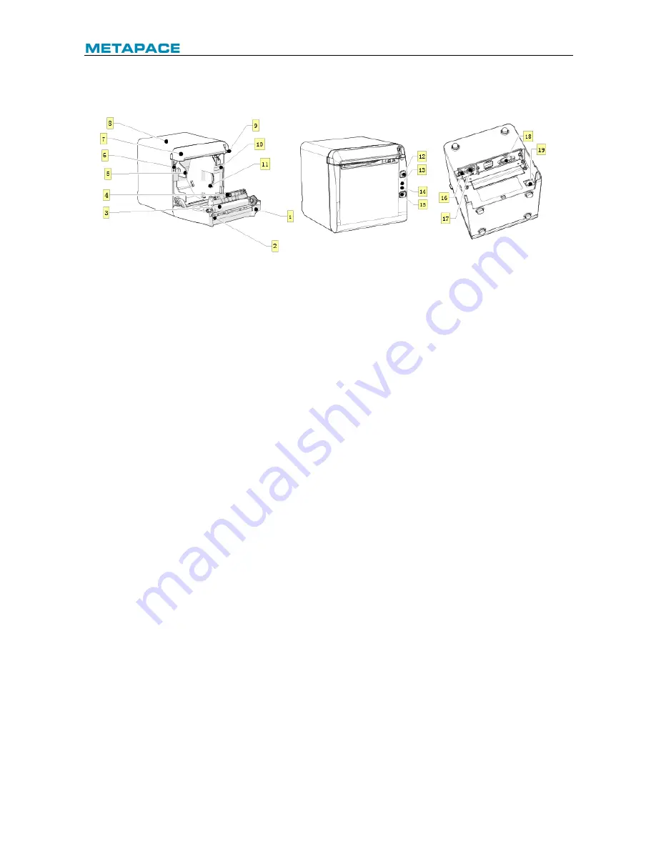
Fig. 3.1-1 Schematic drawing of appearance and modules 

1—Top cover


2—Cutter


3—Platen roller


4—Paper end sensor


5—Paper guide


6—Micro switch


7—Cutter cover


8—Middle cover


9—Cover open spanner


10—Paper cabinet


11—Paper near end sensor


12—FEED button


13—ERROR LED


14—POWER LED


15—POWER button


16—USB


17—Power interface


18—Communication interface


19—Cash drawer interface


Button and component function: 

a  FEED button (12) 

Ø

  Feed paper: 

Printer will feed paper when the feed button is pressed down under normal condition. To 

feed paper continuously, keep pressing the button. 

Ø

  Print configuration sample: 

Pressing  down  the  feed  button  while  turning  on  the  power,  the  printer  will  print  out  the 

configuration sample, which includes print width, print speed, etc. 

Ø

  Enter button configuration mode: 

Press  down  the  feed  button  while  turning  on  the  power,  the  printer  will  print  out  the 

configuration  sample,  and  enter  pause  status  (error  LED  flashes)  after  cutting  paper. 

Keep pressing the feed button at this time, the printer will enter button configuration mode. 

Ø

  Press the button to clear the cutter error: 

Press the button for a short time when a cutter error occurs, the printer will try to clear the 

cutter error automatically. 

b  Error LED (13) 

Indicate  printer  status.  Under  normal  status,  the  error  LED  is  off.  Under  error  status  (e.g. 

paper end, etc.), the error LED flashes. 

c  Power LED (14) 

Indicate printer power status (ON/OFF). 

d  Power button (15) 

Содержание T-40

Страница 1: ...USER S MANUAL Thermal Receipt Printer T 40 ...

Страница 2: ...ion 8 4 1 Unpacking 8 4 2 Printer installation 8 4 3 Power and communication interface 9 4 3 1 Power connection 9 4 3 2 Interface connection 9 4 3 3 USB interface connection 9 4 3 4 Cash drawer connection 9 4 4 Paper roll installation 10 4 4 1 Paper type confirmation 10 4 4 2 Install replace paper roll 10 4 5 Paper near end position adjustment 12 4 6 Power on and self test 13 4 6 1 Power on 13 4 6...

Страница 3: ...l interface 16 6 3 USB interface 18 6 4 Ethernet interface 18 6 5 Double communication interface 19 6 6 Power interface definition 20 6 7 Cash drawer interface signal definition 20 7 Troubleshooting 22 7 1 Printer doesn t work 22 7 2 Error LED and buzzer alarm 22 7 3 Problems during printing 22 8 Power management 23 9 DUMP mode 24 Appendix Button configuration 25 ...

Страница 4: ...r200 Win7 Win8 Win8 1 Win10 Server 2012 POSReady2009 POSReady7 Linux Mac and UPOS middleware Note Windows and Linux drivers support 64 bit operation system 1 2 Features Ø Low noise high printing speed Ø Support continuous paper marked paper Ø Support paper saving water mark upside down two color printing etc Ø Compact size can output paper from the front or the top according to users different dem...

Страница 5: ...r Paper near end sensor Cover position sensor Paper presence sensor Print head temperature sensor Printer voltage detection Cut mode Full cut partial cut Barcode 1D UPC A UPC E CODE 39 CODE 93 CODE 128 EAN8 EAN13 ITF CODABAR 2D PDF417 QR Maxicode Fonts Font A 12 24 Font B 9 17 Kanji font A 24 24 Character set 95 Alphanumeric 14 types of international characters 128 x 68 code page Optional Traditio...

Страница 6: ...ions Saving paper Support Button configuration Support configure the printer without computer Right up side printing Support Water mark printing Support Gray scale printing Support Table 2 1 1 Technical specifications 2 2 Cutter parameters Item Parameter Remarks Cutting method Sliding blade Cutting time 500 ms The time of one cut Cutting interval 3 s 20 cuts minute Max Applicable paper types 0 06 ...

Страница 7: ... black mark must be no more than 15 while the reflectivity of the paper itself should exceed 85 There should be no image between the two marks such as the advertisement etc Caution Please use the recommended paper or its equivalents Using the paper of low quality might affect the print quality and shorten the lifetime of print head Do not stick paper onto the core shaft If the paper is contaminate...

Страница 8: ...int configuration sample Pressing down the feed button while turning on the power the printer will print out the configuration sample which includes print width print speed etc Ø Enter button configuration mode Press down the feed button while turning on the power the printer will print out the configuration sample and enter pause status error LED flashes after cutting paper Keep pressing the feed...

Страница 9: ...detect the paper marks when marked paper is used g Spanner for adjusting paper near end sensor 7 Detect the paper roll status Fast flashing of error LED indicates that the paper will be used out soon and the user should replace the paper roll in time Printer will work normally until paper is used out h Paper guide 5 Adjust the position of paper guide in the cabinet to adapt to different paper widt...

Страница 10: ...times Printer voltage is abnormal Cycle flash 5 times Cycle beep 5 times Cutter error Cycle flash 4 times Cycle beep 4 times Print head lift up Cycle flash 3 times Cycle beep 3 times Paper end Cycle flash 2 times Cycle beep 2 times Paper near end Cycle flash slowly No beep Cannot find mark or mark calibration error Cycle flash slowly No beep Table 3 2 2 LED and indication information Caution The t...

Страница 11: ...ally on the table the incline installation angle should not exceed 5 otherwise the paper near end sensor will not work normally Fig 4 2 1 Horizontally on the table paper output from the front Fig 4 2 2Horizontally on the table paper output from the top 2 Keep the printer far away from water source 3 Do not place the printer in the place exposed to vibration and impact 4 The printer power must be s...

Страница 12: ... the power cord from the printer 4 3 2 Interface connection 1 Ensure that the power switch is turned off 2 Plug the connector into corresponding port and fix it with screw or spring as shown in the figure 3 Connect the other end of cable to the host 4 3 3 USB interface connection 1 Ensure that the power switch is turned off 2 Plug the USB cable into corresponding interface in place as shown in the...

Страница 13: ...hown in the Fig to open the top cover 3 Place the paper roll into the printer 4 Close the top cover Fig 4 4 1 Schematic drawing of paper roll installation replacement Fig 4 4 2 Schematic drawing of paper roll installation replacement Caution Adjust the paper guide according to the paper specification install the paper guide at the position of 57 5 for 57 5 wide paper roll install the paper guide a...

Страница 14: ...l is tightly wound otherwise paper jam or other failure may occur eg Fig 4 3 Failure model Paper roll should be placed stably in the paper cabinet without incline or the printing will be affected Fig 4 4 4 Position of 57 5 Fig 4 4 5 Position of 80 Fig 4 4 5 Operation hole ...

Страница 15: ... 5 Paper near end position adjustment Fig 4 5 1 Schematic drawing of paper near end position adjustment output paper from the front Fig 4 5 2 Schematic drawing of paper near end position adjustment output paper from the front ...

Страница 16: ...and position 2 is for 20 8 mm core shaft of paper roll The position 3 and 4 are for the application that output paper from the front position 3 is for 20 8 mm core shaft of paper roll and position 4 is for 16 2 mm core shaft of paper roll Fig 4 5 3 core shaft of paper roll 4 6 Power on and self test 4 6 1 Power on 1 Ensure that the printer is connected to power 2 Turn on the power switch to power ...

Страница 17: ...tering Hexadecimal dumping mode in the following ways a Open the printer mechanism and turn on the printer while pressing the feed button Release the button after the printer alarms LED flashes and buzzer beeps b Send command GS A 2 The printer first prints Hexadecimal Dump To terminate and then prints the data transmitted from the host in hexadecimal and their corresponding ASCII characters 3 Exi...

Страница 18: ...entify the mark effectively the mark sensor should be cleaned The cleaning steps are as follows 1 Turn off the printer 2 Press the cover open lever to open the top cover 3 Wipe off the dust and stains on the surface of the sensor with soft cotton cloth dipped with pure alcohol it should be wrung out 4 Install the sensor cover after the pure alcohol is completely evaporated then close the top cover...

Страница 19: ...ace setting status via printing configuration sample The default settings of serial interface are as follows Baud rate 115200bps Data bits 8 Parity none Stop bit 1 Handshake DTR DSR 6 2 Parallel interface The parallel interface can work in IEEE 1284 compatible mode or nibble mode The interface is 36PIN socket Interface definition Pin No Signal source Signal definition 1 H nStrobe 2 H Data 0 Least ...

Страница 20: ... letter n in front of signal name indicates that the low level is effective In data transmission the host should not ignore Busy signal otherwise print data may be missing If the host cannot provide all the signal lines listed in the table above the communication may fail Parallel interface signal adopts TTL level the rise and fall time of the signal from the host must be controlled within 0 5 s w...

Страница 21: ...ds to install the USB driver provided by the manufacturer Windriver mode is also called class mode it is no need to install drivers and the user can use Microsoft s generic driver The factory setting of printer is API mode the user needs to adjust it to class mode if the printer is going to work under a Linux system 6 4 Ethernet interface 1 Interface features Ø Support 10 100 BASE T communication ...

Страница 22: ...C Not connected 8 NC Not connected Table 6 4 1Ethernet interface definition 6 5 Double communication interface Double communication interface support serial interface and Ethernet interface at the same time 1 The serial interface of the printer is compatible with RS 232 standard and its interface socket is DSUB 9 socket Pin definition is as following PIN No Signal definition PIN1 Not connected PIN...

Страница 23: ...face definition 2 Main control board power interface definition 24V DC Fig 6 6 2 Schematic drawing of 24V power interface 6 7 Cash drawer interface signal definition 1 Electrical features Ø Driving voltage DC 24 V Ø Driving current Max 1 A Ø Cash drawer status detection signal L 0 0 5 V H 3 3 V 2 Cash drawer interface socket uses RJ 11 6P connector Fig 6 7 1 Schematic drawing of cash drawer interf...

Страница 24: ...etection signal 4 VDR Cash drawer driving power 5 DRAWER 2 Cash drawer 2 driving signal 6 GND Circuit share ground Table 6 7 1 Cash drawer interface definition Caution Do not connect or disconnect communication cable plug when the printer is powered on Communication cable should be far away from strong current Communication cable should adopt shielded cable ...

Страница 25: ...ping The printer has serious malfunction Contact your local dealer or the manufacturer Table 7 2 1 Troubleshooting of error LED and buzzer alarm 7 3 Problems during printing Problem Possible causes Solution Paper cannot be sent out normally Paper jam Open the top cover check paper path and cutter and clear paper jam Printer starts printing but stops suddenly during printing Paper jam Open the top ...

Страница 26: ...ter will enter standby mode after powering on the printer or completing printing task Printer will enter sleep mode if there is no printing task for 2 minutes in standby mode Printer will awake automatically and enter active mode when a printing task comes and will enter standby mode again after completing the printing task ...

Страница 27: ... LED flashes Pay attention to keep paper in the paper cabinet The printer will print out the following contents after the above operation Hexadecimal Dump To terminate hexadecimal dump press FEED button three times The printer already entered the DUMP mode at this moment Method to exit from the DUMP mode continuously press the FEED button for three times and the printer will print out the followin...

Страница 28: ...ion 3 CONFIGURATION Exit Without Save 1 Exit With Save 2 Communication 3 Back To Last Menu 1 USB Interface 2 USB mode API MODE Back To Last Menu 1 WinDriver Mode 2 API Mode 3 Serial Interface 3 SERIAL INTERFACE Back To Last Menu 1 Baud Rates 2 BAUD RATES 115200bps Back To Last Menu 1 9600bps 2 19200bps 3 38400bps 4 57600bps 5 ...

Страница 29: ...Parity 3 PARITY NONE Back To Last Menu 1 None 2 Odd 3 Even 4 Data Bits 4 DATA BITS 8 Bits Back To Last Menu 1 7Bits 2 8Bits 3 Stop Bit s 5 STOP BITS 1Bit Back To Last Menu 1 1 Bit 2 2 Bits 3 Handshaking 6 HANDSHAKING DTR DSR Back To Last Menu 1 DTR DSR 2 XON XOFF 3 ...

Страница 30: ...FER SIZE 4K Bytes Back To Last Menu 1 4 kBytes 2 45 Bytes 3 64 KBytes 4 Mechanism Hardware 4 HARDWARE SETTINGS Back To Last Menu 1 Mark Sensor 2 MARK SENSOR Disable Back To Last Menu 1 Enable 2 Disable 3 Cutter 3 CUTTER Back To Last Menu 1 Cut Mode Settings 2 CUTMODESETTINGS Default Cut Mode Back To Last Menu 1 Enable 2 Disable 3 ...

Страница 31: ...nu 1 Cut paper when cover is closed is closed 2 No cut paper when Cover is closed 3 Cut paper when Power on 4 No cut paper when Power on 5 Disable 6 Buzzer 4 BUZZER Enabled Back To Last Menu 1 Enable 2 Disable 3 Print Settings 5 PRINT SETTINGS Back To Last Menu 1 Darkness Settings 2 DARKNESS SETTING Normal Back To Last Menu 1 Low 2 Normal 3 High 4 ...

Страница 32: ...PAPER ROLL WIDTH 80 0 mm Back To Last Menu 1 57 5 mm 2 80 0 mm 3 82 5 mm 4 Left Margin 4 LEFT MARGIN 7 mm Back To Last Menu 1 0 mm 2 1 mm 3 3 mm 4 5 mm 5 7 mm 6 9 mm 7 Right Margin 5 Right margin 9 mm Back To Last Menu 1 0 mm 2 1 mm 3 3 mm 4 5 mm 5 7 mm 6 ...

Страница 33: ... 7 Code page settings Back To Last Menu 1 Print All Code pages 2 Select A Code page 3 Save Paper Level 8 SAVE PAPER LEVEL Back To Last Menu 1 Disable 2 25 3 50 4 75 5 100 6 Paper Sensor Settings 6 PAPER NEAR END SETTING S Back To Last Menu 1 Paper Low Alarm 2 Paper low alarm Enable Back To Last Menu 1 Enable 2 ...

Страница 34: ... SENSER Enabled Back To Last Menu 1 Enable 2 Disable 3 Set Default Config 7 SET DEFAULT CONFIGURATION Back To Last Menu 1 Set Printer To Default Configuration 2 FONT A FONTB Settings 8 Current Font FONT A Back To Last Menu 1 Select FONT A 2 Select FONT B 3 Select UD FONT A 4 Select UD FONT B 5 Beep settings 9 Beep settings Disabled Back To Last Menu 1 Enable External Herald 2 ...

Страница 35: ...ings 10 Testpage up to down print Disabled Back To Last Menu 1 Enable 2 Disable 3 Enter code then hold Button Down at least 1secondto validate Sensor Test 4 Sensor Test Mode ERROR LED state will change according to sensorstate To EXIT hold button down at least 1second Print NV Bitmap 5 Cutter Test 6 Print Statistics 7 T 40 STATISTICS CUT 0 TCUT 0 LFS TLFS ...

Страница 36: ...T 40 User s Manual 33 ONTIME 0 E05Configuration 8 E05CONFIGURATION Reset JK E04 Config 1 I Print Settings 2 IP Address MAC Address Subnet Mask GATEWAY Print Port ...

Отзывы: