background image

30

PRM FH | Version 1.04 | EN

Maintenance, servicing and repair

10.1Hydraulic system

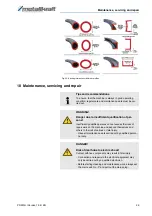
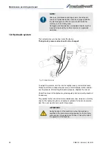
The hydraulic pressure has been set at the factory.

The hydraulic pressure value should not be changed!


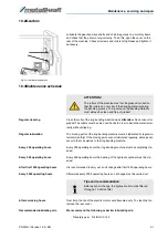
Fig. 23: Hydraulic pressure

To adjust the pressure, turn the lock nut slightly loosely (counterclockwise). 
Clockwise rotation increases the pressure, counterclockwise rotation decrea-
ses the pressure. After setting the desired pressure, retighten the lock nut.

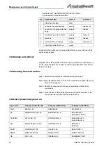
Check the oil level of the hydraulic system regularly and top up wit hydraulic oil 
if necessary.

The gearbox for the roller drive is also maintenance-free. However, a monthly 
check of the hydraulic system and hydraulic cylinders for leaks is recommen-
ded. The cover must be removed for this purpose.

NOTE!

After care, maintenance and repair work, check that all 
covers and protective devices have been properly fitted to 
the machine again and that no tools are left inside the 
machine or in its working area. 
Damaged protective devices and equipment parts must be 
repaired or replaced by customer service or a specialist 
workshop.

ATTENTION!

During transport of the machine or when the machine is 
switched to the horizontal working position for the first time, 
some excess oil may leak from the tank. This will not affect 
the operation of the machine. 

Содержание PRM 50 FH

Страница 1: ...PRM 50 FH Operating Instructions PRM 50 FH Ring Bending Machine hydraulic PRM 60 FH...

Страница 2: ...gtheoperating instructions Original Instructions Edition 29 09 2020 Version 1 04 Language English Author ES Indications regarding the copyright Copyright 2020 St rmer Maschinen GmbH Hallstadt Germany...

Страница 3: ...llers 21 9 3 Adjusting the lateral guide rolls 22 9 4 Profiles bending 22 9 5 Bending rolls 24 9 6 Bending tolerances of different profiles 28 10 Maintenance servicing and repair 29 10 1 Hydraulic sys...

Страница 4: ...t The contents of this manual are protected by copyright Their use is permitted when using the machine Any further use is not permitted without the written permission of the manufacturer We hereby app...

Страница 5: ...onditions of the manufacturer and the legal regula tions valid at the time of the conclusion of the contract apply 2 Safety This section provides an overview of all major safety packages for personal...

Страница 6: ...ther the operating instructions he has prepared comply with the cur rent state of the regulations and adjust them if necessary The operator must clearly regulate and determine the responsibilities for...

Страница 7: ...regulations the electrician is in a po sition to carry out work on electrical installations and to recognize and avoid possible dangers independently The electrician is specially trained for the work...

Страница 8: ...instructions The safety markings attached to the ring bending machine must not be remo ved Damaged or missing safety markings can lead to malfunctions personal injury and property damage They are to b...

Страница 9: ...assumes no liability for design and tech nical changes to the ring bending machine The improper use of the ring ben ding machine as well as the disregard of the safety regulations or the operating in...

Страница 10: ...CE marking of the ring bending machine PRM 50 FH PRM 50 FH PRM 60 FH Shaft diameter 50 mm 60 mm Roller on the top 152 mm 215 mm Roller on the bottom 162 mm 215 mm Speed 4 5 rpm 4 rpm Hydraulic pressur...

Страница 11: ...s as well as for sufficient strength and load capacity WARNING Severe or fatal injuries may occur if parts of the machine tumble or fall down from the forklift truck pallet truck or from the transport...

Страница 12: ...sport Fig 4 Transport of the ring bending machine 5 2 Packaging All packaging materials and packaging aids used in the machine are recycla ble and must always be recycled Cardboard packaging component...

Страница 13: ...rection hori zontal vertical lateral The possibility of setting up the ring bending machine horizontally and vertically Mobile control panel with foot control Operating instructions Optional accessori...

Страница 14: ...t and maintenance work The site must have good lighting Dimensions Fig 6 Dimensions of the ring bending machines PRM 50 FH left and PRM 60 FH right The following size specifications should be taken in...

Страница 15: ...side of the machine to the wall min 1000 mm de pends on the size of the materials to be bent Hazardous areas on the machine Fig 8 Hazardous areas on the ring bending machine A Inside the machine hydra...

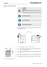
Страница 16: ...and even out any slight unevenness Step 2 Place the ring bending machine on a level firm and vibration free sur face Step 3 Fasten the ring bending machine to the surface with ground anchors Step 4 Co...

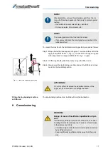
Страница 17: ...installation 8 Commissioning NOTE After installation remove the protective agent from the rol lers which has been applied in the factory to protect against rusting Use a cloth and usual solvents e g...

Страница 18: ...drugs or medication and or in the event of fatigue or illnesses affecting concentration The machine may only be operated by qualified personnel Use hearing protection Use protective gloves Wear safet...

Страница 19: ...look at the direction of rotation when the mo tor runs out In case of wrong direction of rotati on of the motor Step 2 If the motor rotates in the wrong direction replace two phases at the connection...

Страница 20: ...r down 5 Pedals Right pedal Rotation of the rollers movement of the workpiece to the right Left pedal Rotation of the rollers workpiece movement to the left 5 Digital display optional Fig 12 right Dis...

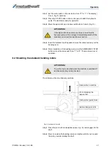
Страница 21: ...machine is out of operation 9 2 Mounting the standard bending rollers The rollers must be mounted very carefully Fig 14 Assembly of the rolls Step 1 Press the pin in with a screwdriver arrow Fig 14 an...

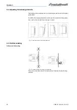
Страница 22: ...In addition the lateral guide rollers are also used for special machining opera tions such as the manufacture of springs or spirals Fig 15 Adjustment options for the lateral guide rolls 9 4 Profiles b...

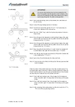
Страница 23: ...nt and to bend slightly Fig 17 Form C Step 9 Again move the profile between the rollers and bend Step 10 To also pre bend the other end of the profile the steps just described must be repeated Fig 17...

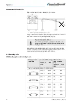
Страница 24: ...profiles in order to avoid overstressing the material and the ring bending machine 9 5 Bending rolls 9 5 1Bending options with bending rollers Tips and recommendations At a vertically positioned ring...

Страница 25: ...power specifications refer to 24 kg m2 sheet bending limit 1 The smallest possible bending radius depends on how strong the mate rial deformation may be WARNING Never use profiles with a greater mater...

Страница 26: ...be controlled in such a way that the workpiece finds a good place between the rollers and can advance under slight pressure In the case of the majority of profile bars a considerable swelling will be...

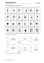
Страница 27: ...Operation PRM FH Version 1 04 EN 27 9 5 3Possible applications for bending rollers Fig 20 Application examples for bending rolls Fig 21 Special rollers and special guide rollers for bending profiles...

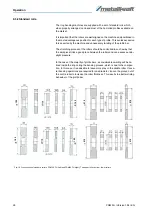
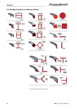
Страница 28: ...28 PRM FH Version 1 04 EN Operation 9 6 Bending tolerances of different profiles Fig 22 Bending tolerances of different profiles...

Страница 29: ...er sons Insufficiently qualified persons cannot assess the risks of repair work on the machine and expose themselves and others to the risk of serious or fatal injury Have all maintenance work carried...

Страница 30: ...arbox for the roller drive is also maintenance free However a monthly check of the hydraulic system and hydraulic cylinders for leaks is recommen ded The cover must be removed for this purpose NOTE Af...

Страница 31: ...ry 200 operating hours Every 200 operating hours the ring bending machine must be completely cle aned Every 500 operating hours Every 500 operating hours the bearing of the hydraulic cylinder must be...

Страница 32: ...ions Step 4 Close the door of the electrical box and connect the machine to the mains Start the machine and check all functions 10 6List of potencial types of oil No Equipment part Interval Lubricant...

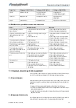
Страница 33: ...ction 2 Contact the dealer manufacturer The motor is still runnig but the ring bending machine is not moving 1 The motor is turning in the wrong di rection 2 The oil level is low 1 Check the direction...

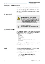
Страница 34: ...is missing shipping will be at the discretion of the supplier In formation on the machine type article number and year of manufacture can be found on the type plate which is attached to the machine E...

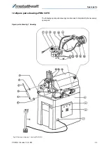
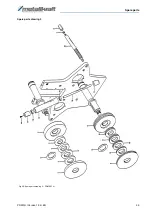
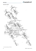
Страница 35: ...ersion 1 04 EN 35 12 2Spare parts drawings PRM 50 FH The following spare parts drawings are intended to help identify the necessary spare parts Spare parts drawing 1 Housing Fig 25 Spare parts drawing...

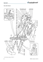
Страница 36: ...36 PRM FH Version 1 04 EN Spare parts Fig 26 Spare parts drawing 2 PRM 50 FH Spare parts drawing 2...

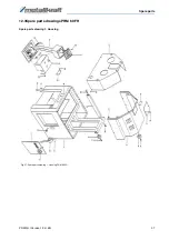
Страница 37: ...Spare parts PRM FH Version 1 04 EN 37 12 3Spare parts drawings PRM 60 FH Spare parts drawing 1 Housing Fig 27 Spare parts drawing 1 Housing PRM 60 FH...

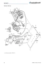
Страница 38: ...38 PRM FH Version 1 04 EN Spare parts Spare pars drawing 2 Fig 28 Spare parts drawing 2 PRM 60 FH...

Страница 39: ...Spare parts PRM FH Version 1 04 EN 39 Spare parts drawing 3 Fig 29 Spare parts drawing 3 PRM 60 FH...

Страница 40: ...40 PRM FH Version 1 04 EN Spare parts Spare parts drawing 4 Fig 30 Spare parts drawing 4 PRM 60 FH...

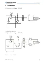
Страница 41: ...s PRM FH Version 1 04 EN 41 13 Circuit diagrams 13 1Hydraulic circuit diagram PRM 50 FH Fig 31 Hydraulic circuit diagram PRM 50 FH 13 2 Hydraulic circuit diagram PRM 60 FH Fig 32 Hydraulic circuit dia...

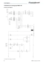
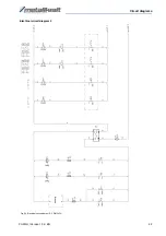
Страница 42: ...42 PRM FH Version 1 04 EN Circuit diagrams 13 3Electrical circuit diagrams PRM 50 FH Fig 33 Electrical circuit diagram 1 PRM 50 FH Electrical circuit diagram 1...

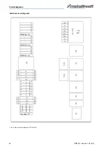
Страница 43: ...Circuit diagrams PRM FH Version 1 04 EN 43 Electrical circuit diagram 2 Fig 34 Electrical circuit diagram 2 PRM 50 FH Bremse...

Страница 44: ...44 PRM FH Version 1 04 EN Circuit diagrams Electrical circuit diagram 3 Fig 35 Electrical circuit diagram 3 PRM 50 FH Grounding Grounding Grounding Grounding...

Страница 45: ...Circuit diagrams PRM FH Version 1 04 EN 45 13 4Electrical circuit diagrams PRM 60 FH Electrical circuit diagram 1 Fig 36 Electrical circuit diagram 1 PRM 60 FH...

Страница 46: ...46 PRM FH Version 1 04 EN Circuit diagrams Electrical circuit diagram 2 Fig 37 Electrical circuit diagram 2 PRM 100 FH Bremse...

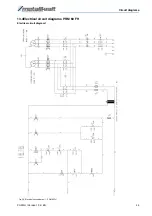
Страница 47: ...Circuit diagrams PRM FH Version 1 04 EN 47 Electrical circuit diagram 3 Fig 38 Electrical circuit diagram 3 PRM 60 FH Grounding Grounding Grounding Grounding...

Страница 48: ...e complies with all relevant provisions of the above mentioned Directive as well as the other applicable Directives hereaf ter including any changes in force at the time of declaration Relevant EU dir...

Страница 49: ...Notes PRM FH Version 1 04 EN 49 15 Notes...

Страница 50: ...www metallkraft de...

Отзывы: